CO-Guard
ENMET
Manual Release Date – June 8, 2017
P a g e
| 1
Manual Part No. – 80002-044
Table of Contents
1.0
I
NTRODUCTION
.................................................................................................................................................................... 2
1.1 Unpack ............................................................................................................................................................................................. 2
1.2 Check Order ..................................................................................................................................................................................... 2
1.3 Serial Numbers................................................................................................................................................................................. 2
2.0
C
OMPONENTS OF THE
CO-G
UARD
........................................................................................................................................ 3
2.1 CO-G
UARD
elements........................................................................................................................................................................ 3
2.2 CO-G
UARD
Operational Features .................................................................................................................................................... 3
2.3 Circuit Board Features ..................................................................................................................................................................... 5
3.0
I
NSTALLATION
..................................................................................................................................................................... 6
3.1 Mounting CO-G
UARD
...................................................................................................................................................................... 6
3.2 Wiring the CO-G
UARD
..................................................................................................................................................................... 7
3.2.1 Air Supply ....................................................................................................................................................................................................... 7
3.2.2 Power Supply .................................................................................................................................................................................................. 7
3.2.3 Relay Contacts ................................................................................................................................................................................................ 8
4.0
O
PERATION
......................................................................................................................................................................... 9
4.1 Start Up CO-G
UARD
........................................................................................................................................................................ 9
4.1.1 Typical Start Up .............................................................................................................................................................................................. 9
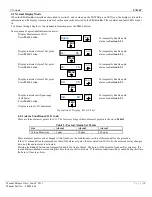
4.2 Normal Display Mode .................................................................................................................................................................... 10
4.2.1 Alarm Conditions CO-G
UARD
....................................................................................................................................................................... 10
5.0
M
AINTENANCE
.................................................................................................................................................................. 11
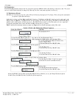
5.1 Maintenance Menus ....................................................................................................................................................................... 11
5.2 Calibration of the CO-G
UARD
........................................................................................................................................................ 13
5.2.1 Exit Maintenance Menu ................................................................................................................................................................................ 14
5.2.2 Zero Adjust.................................................................................................................................................................................................... 14
5.2.3 Gas Span ....................................................................................................................................................................................................... 15
5.2.4 Alarm Set Points ........................................................................................................................................................................................... 16
5.2.5 Span Set ........................................................................................................................................................................................................ 16
5.4 Sensor Replacement ....................................................................................................................................................................... 17
6.0
R
EPLACEMENT
P
ARTS
....................................................................................................................................................... 18
7.0
T
ECHNICAL
D
ATA AND
S
PECIFICATIONS
............................................................................................................................. 18
List of Tables
Table 1 : Relay Failsafe Settings .................................................................................................................................................. 8
Table 2: Factory Alarm Set Points ............................................................................................................................................. 10
Table 3: CO-Guard Maintenance Menus Sequence ................................................................................................................... 11
Table 4: Calibration Gas ............................................................................................................................................................ 14
List of Illustrations
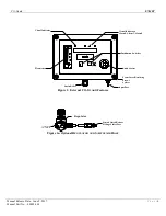
Figure 1: External CO-Guard Features ........................................................................................................................................ 4
Figure 1a:
Optional
Regulator and Sample Air Hose .................................................................................................................. 4
Figure 2: CO-Guard Circuit Board Features ................................................................................................................................ 5
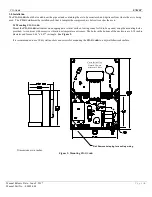
Figure 3: Mounting CO-Guard .................................................................................................................................................... 6
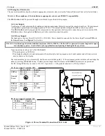
Figure 4: Power Terminal Connections CO-Guard ...................................................................................................................... 7
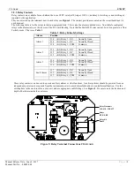
Figure 5: Relay Terminal Connections CO-Guard ...................................................................................................................... 8
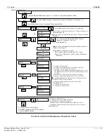
Figure 6: CO-Guard Maintenance Menu Flow Chart ................................................................................................................ 12
Figure 7: Calibration Adapter .................................................................................................................................................... 13
Figure 8:
CO-Guard
Sensor Replacement ................................................................................................................................ 17
Reference Information:
N
OTE
: [important information about use of instrument]
C
AUTION
:
[affects equipment – if not followed may cause damage to instrument, sensor etc.…]
W
ARNING
:
[affects personnel safety – if not followed may cause bodily injury or death.]
Earth Ground

