


Code: I.H4.V10.3003
Installation and Maintenance Manual
Version: 07
13 / 66
Ennera Energy and Mobility, S.L.
This document contains confidential information which is property of Ennera Energy and Mobility, S.L. The copy, transmission or use by other people, of the whole document or
part of its contents, is not allowed without written permission from Ennera Energy and Mobility S.L.
5.2.
Ennera design multi-section tower assembly
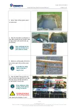
1.
Put the tower sections in a
sequential way close to the foundation.
The tower first section
should be located next to
the foundation.
2.
Join the first section and the tower
base plate with the J bolt M20x500 as
shown in the figure.
Place the base plate in the
middle of the lifting
direction as shown in the
figure.
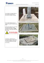
3.
Place the first section and the tower
base plate over the foundation bolts
(FD-1) as shown in the figure.
Make sure that the base
plate is aligned with the
lifting direction.
4.
Fix the tower base plate to the
foundation bolts with M30 nuts.
Do not tight them fully.
Before that, alignment of
foundation bolts and base
holes should be verified.
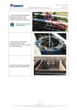
5.
Manually check the clearance of first
section holes and tower bolts:
•
Put one M30 nut on the guide bolt in
order to hold the tower base section
during the checking process.
•
Hold the tower base section from
top of it and pull it up.
•
Ensure that the foundation bolts
pass freely through the base holes.
If there is a misalignment,
correct the position of the
base plate with a hammer.
T0
T1
Lifting
direction
T0
T1
FD-1
First
section
Guide
bolt