4
2 Intended use
The EnOcean wireless plug-in module can
be used to operate the ventilation unit with
optional EnOcean components (according to
EnOcean wireless standard). Once the plug-
in module has been installed, the EnOcean
wireless sensors and operating units can be
learnt via the comfort control unit, web server
or commissioning software (installer).
Read the safety instructions in the instal-
lation instructions for the ventilation unit
before connecting the EnOcean compo-
nent to the ventilation unit. Follow the
instructions.
3 Safety instructions
Danger from electric shock:
Before removing the front cover,
shut down all supply circuits (de-
activate the mains fuse) and se-
cure so they cannot be switched
back on. Attach warning sign in
clearly visible place.
Danger of injury when fans
are running:
Before removing
the front cover, wait until both
fans have stopped.
Danger of burning from hot
housing parts on units with
PTC heat register:
After removing the front cover,
do not touch the heat register.
First wait until the heat regis-
ter and the housing parts have
cooled off.
Store packaging material out of
the reach of children
Risk of
suffocation if swallowed.
4 Installing E-SM plug-in module
NOTICE
If the connection cables are too short, the
electronic slide-in module cannot be fully
pulled out/fitted.
Ensure connection cables
of a sufficient length inside the ventilation unit.
NOTICE
Danger of short-circuits/damage to unit
should water enter the electronics com-
partment.
Ensure a correct, sealed line feedthrough
through the cable feedthrough.
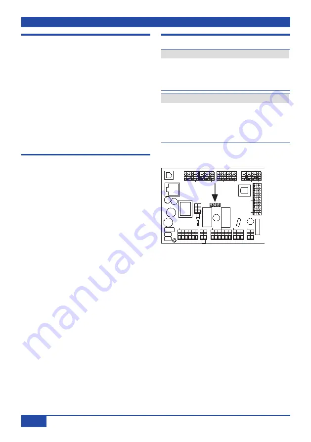
Main circuit board slot X01 for optional
E-SM plug-in module
MAICO
Steuerung KWL
1234
5
X7
Bypass
T1
T2
T3
T4
X8
Fühler
X9
Abluft
Zuluft
X10
Digital
RS485
X11
X12
Sensoren
RLS
X13
X1
PE
N
L
Netz
PE
N
L
Option
X3
1
2
X4
PE
N
L
PE
N
L
Zuluft
Abluft
X5
PE
N
L
Heizregister
X6
1
2
Kontakt
Ethernet
US
B
2
1
X2
NC
NC
3.3
SD
SC
A
B
12V
LD2LD1
S1+S2-
LD3
24V
24V
W3
XO1
A2
XO1
Positioning E-SM plug-in module on main
circuit board A2 and connecting
1. Shut down all supply circuits.
2. Remove front cover(s)
Installation
instructions for ventilation unit.
3. Lift electronic slide-in module and pull
out of the electronics compartment. Hang
slide-in module in fitting studs (if present)
Installation instructions for ventilation
unit.
4. Carefully position E-SM plug-in module on
slot X01 of main circuit board
until spacer
bolts fully engage
– correctly insert all
spacer bolts.
5. Correctly push through cable feedthrough
of ventilation unit.
6. Guide antenna cable (approx. 2 m) through
cable feedthrough into ventilation unit.
Check for leaks and remedy any found.


