USER MANUAL V1.12
EnOcean GmbH
Kolpingring 18a
82041 Oberhaching
Germany
Phone +49.89.67 34 689-0
Fax +49.89.67
34
689-50
info@enocean.com
www.enocean.com
Subject to modifications
PTM 230 User Manual V1.12
June 4, 2008 2:02 PM
Page 6/12
PTM 230
2
FUNCTIONAL DESCRIPTION
2.1
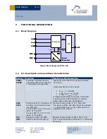
Block Diagram
Figure: Block diagram of PTM 230
2.2
Pin Description and operational characteristics
Symbol Function
Operational Characteristics
PWR1,
PWR2
Inputs for EnOcean energy
converter ECO 50 or ECO 100
or equivalent energy pulse
Maximum wire length to energy converter:
5cm each
Requirements for energy pulse:
E
Pulse
> 0.25mWs
2.5V
≤
U
max,Pulse
≤
5.5V
0.3ms
≤
T
Pulse
≤
11ms
(voltage measured with module connected;
required pulse width depends on voltage,
pulse shape and source impedance)
SW1,
SW2
Digital inputs for simulation of
O-button and I-button signal
of a PTM 200
Connect SW1 to Vcc for simu-
lation of “I-button”
Connect SW2 to Vcc for simu-
lation of “O-button”
Maximum wire length to Vcc: 3cm each
The signal at SW1 and SW2 must be available
> 100µs before and > 10ms after energy is
supplied to the module.
Vcc
Supply for SW1 and SW2
Maximum wire length to SW1, SW2: 3cm
ANT
Pad for antenna mounting
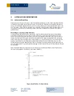
87mm whip antenna as defined in 3.1 Antenna
Mounting
Processor
HF
Power
Converter
Data
DC Power
Processor
HF
Power
Converter
Data
DC Power
Polarity
SW1
SW2
Vcc
PWR 1
PWR 2
ANT
Processor
HF
Power
Converter
Data
DC Power
Processor
HF
Power
Converter
Data
DC Power
Polarity
SW1
SW2
Vcc
PWR 1
PWR 2
ANT


