USER MANUAL V1.12
EnOcean GmbH
Kolpingring 18a
82041 Oberhaching
Germany
Phone +49.89.67 34 689-0
Fax +49.89.67
34
689-50
info@enocean.com
www.enocean.com
Subject to modifications
PTM 230 User Manual V1.12
June 4, 2008 2:02 PM
Page 9/12
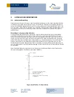
PTM 230
(tinned)
bared, twisted and tinned
Cu-wire, 0.14 mm
2
cross section
according to VDE 0812 or
0245 Cl.5 or Cl. 6
Isolation: PVC mixture TI2,
to VDE 0207-4
(tinned)
bared, twisted and tinned
Cu-wire, 0.14 mm
2
cross section
according to VDE 0812 or
0245 Cl.5 or Cl. 6
Insulation: PVC mixture TI2, according
to VDE 0207-4
3
APPLICATION INFORMATION
3.1
Antenna Mounting
Positioning and choice of receiver and transmitter antennas are the most important factors
in determining system transmission range. The PTM 230 modules are supplied without an-
tenna. For standard applications the use of a whip antenna is recommended (87 mm/ 0.14
mm
2
Cu-wire). This antenna enables very compact unit with good radio characteristics. For
mounting the antenna, the following notes should be considered to optimize the system
performance:
Mounting a 1/4-wave whip antenna:
For good transmit performance, great care must be taken about the space immediately
around the antenna since this has a strong influence on screening and detuning the an-
tenna. The antenna should be drawn out as far as possible and must never be cut off. Pri-
marily, the far end of the wire should be mounted as far away as possible from all metal
parts, PCB strip lines and fast logic components (e.g. microprocessors). To avoid radio fre-
quency hash from the motherboard, which desensitizes the unit, PCB strip lines on the
motherboard should be designed as short as possible, and using PCB ground plane layer is
also recommended. To avoid possible damage to the module the end of the antenna should
be insulated.
Note that 868 MHz whip antennas do not show any directional effects under free-field ra-
dio-wave propagation conditions (spot-wise radiator).
Figure: Specification of whip antenna


