background image

Dimension Drawings


Installation and Operation Manual  - COMTEC

® 

/


OXITEC

®

 DustEx 

28 

Doc.-ID: COM_OXI_Dust_11022020 

B.3 

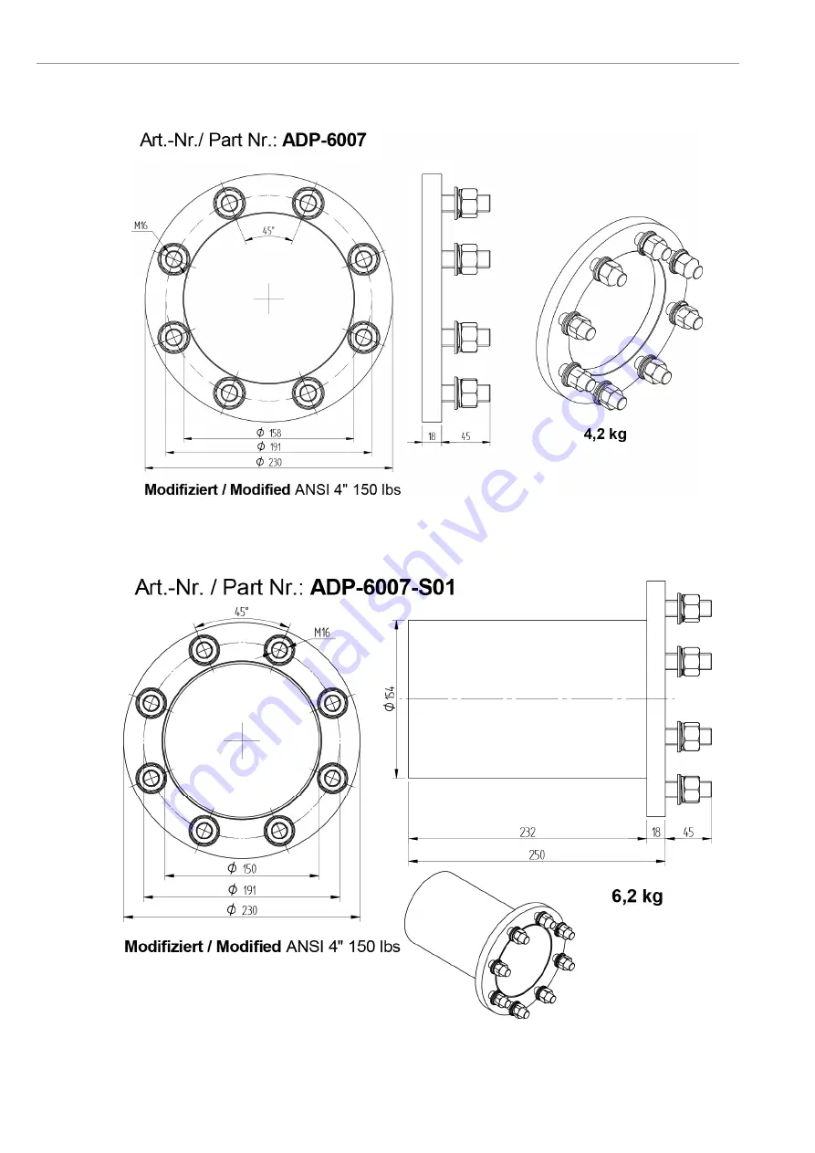
Counter Flange Dimensions 


Figure 47

 - Dimensions of counter flange ADP-6007 for KES600X 


Figure 48

 - Dimensions of counter flange ADP-6007-S01 for KES600X 

Summary of Contents for COMTEC 6000 DustEx

Page 1: ..._OXI_Dust_11022020 Installation and Operation Manual COMTEC 6000 ATEX DustEx O2 COe Analyzer System OXITEC 5000 ATEX DustEx O2 Analyzer System Version 05 OXITEC Software Version 4 13 COMTEC Software Version 4 13 ...

Page 2: ...d troubleshooting To work safely with the analyzer become familiar with all warnings safety instructions and maintenance tasks of this manual Symbols used in this Manual Important information as well as safety instructions are emphasized by the below mentioned symbols Make sure that all safety advice and warnings are observed at all times Warning Follow all instructions in this manual Consider Inf...

Page 3: ... 1 4 2 6 COe Measuring Ranges Scaling 2 4 2 7 COe Sensor Calibration values 2 4 2 8 Time per test gas apply 2 4 2 9 Delay time to process 2 4 2 10 Pre purge time 2 4 2 11 Automatic Calibration ACAL 1 4 2 12 ENOTEC REMOTE 2 4 2 13 Measuring units 2 4 2 14 Language 2 4 2 15 Change system code 2 4 2 16 Load factory settings 3 4 2 17 Set COe measurement to off on 3 4 2 18 Service 3 4 3 System Checks 4...

Page 4: ......

Page 5: ... between both systems Info References to the COe sensor are only applicable to the COMTEC 6000 DustEx analyzer system 1 2 System Overview Figure 1 System overview Electronic unit SME5 IP66 Safe Area Max ambient temp 20 C to 55 C 4 F to 131 F In Situ measuring probe IP6X Potentially explosive atmosphere Dust Ex Max ambient temp 20 C to 70 C 4 F to 158 F Pneumatic cable Duct combustion chamber O2 pr...

Page 6: ...ue gases of combustion plants or in comparable inert gas mixtures If oxidizable gas components are contained in these processes contact ENOTEC For reasons of safety and the possibility of accidents unauthorized conversions and modifications of the system are prohibited Warning The system cannot be used to determine the O2 or O2 COe concentration in combustible gases or in a location where combusti...

Page 7: ...e temperature controller fail safe heater control unit article no HCU 0001 After a switch off of the heating element the heater control unit must be reset manually by the user The probes KES6001 and KES6002 are certificated after Directive 2014 34 EU Equipment indended for use in potentially explosive atmospheres The products contain the following markings ll 2D Ex tb IIIC T133 C T141 C Db The num...

Page 8: ...ture serial number order number and system order code The system order code contains detailed system information which is detailed in the system test report and supplied with the system Nameplate of the SME 53 electronic unit COMTEC 6000 DustEx OXITEC 5000 DustEx Nameplate of the SME 54 electronic unit COMTEC 6000 DustEx OXITEC 5000 DustEx Nameplate of the DustEx probe COMTEC 6000 DustEx OXITEC 50...

Page 9: ...als are specified from 0 08 mm AWG 26 to 2 5 mm AWG 14 If wire end ferrules are used the next smaller size is required Before removal of the electronic terminal cover the line voltage must be switched off The line voltage to the electronic unit must be switched on again after the cover is back in position After installation power conducting parts may not be accessible 2 1 Installation Requirements...

Page 10: ...ing radius FEP 0007 Rmin 234 mm FEP 0008 Rmin 282 mm Temp during installation Temp during operation Cross the probe signal cable FEP 0007 08 at a right angle to the power supply cables No Function Diameter Colors Info 1 O2 measuring cell 2 x 0 75 mm 2 white brown brown With shield 2 Thermocouple 1 2 x 0 75 mm 2 green white With shield 3 Thermocouple 2 2 x 0 75 mm 2 green white With shield 4 Probe ...

Page 11: ...ching the terminal cover After the installation has been completed live parts may no longer be accessible Figure 5 Access to the Terminals To connect the wires follow step 1 to 3 Figure 6 Instruction for the connection of the terminals 2 4 Fitting of Ferrite Sleeves In order to avoid cable related disturbances to the electronic unit the supplied ferrite sleeves are to be fitted CE conformity is in...

Page 12: ......

Page 13: ...e the same voltage as on the power supply input on contacts 1 3 Grounding 19 A B System Error 4 PE protection earth 20 A B Output A O2 measuring range 5 PE protection earth 21 A B Limit Alarm 1 O2 6 FE functional earth 22 A B Limit Alarm 2 COe Shielding Probe solenoid valve Power supply probe heater 115V 23 A Internal Power supply for probe solenoid valve 115VAC 8 L black 23 B 9 N blue 24A L grey ...

Page 14: ...Installation Installation and Operation Manual COMTEC OXITEC DustEx 2 Doc ID COM_OXI_Dust_11022020 2 6 Electrical Wiring Diagram OXITEC DustEx Figure 8 Wiring diagram of OXITEC 5000 DustEx O2 analyzer ...

Page 15: ...Installation and Operation Manual DustEx Installation Doc ID COM_OXI_Dust_11022020 3 2 7 Electrical Wiring Diagram COMTEC DustEx Figure 9 Wiring diagram of COMTEC 6000 DustEx O2 COe analyzer ...

Page 16: ...ature pressure and all other process conditions must be in accordance with the specification Leave enough space for insertion removal of the probe and protection tube if supplied and ensure access to the measuring probe and or connecting box Before cutting a hole in the flue gas duct make sure that the inside of the duct has enough space for probe installation and that no soot is blown out nearby ...

Page 17: ...ounted at an angle of 1 3 2 so that condensed flue gas elements can flow back into the duct Figure 10 Mounting of the counter flange 2 10 Adjusting the V shield Info Before installing the probe the direction of flue gas flow 3 must be determined and the filter head assembly turned to such a position that the flue gas flow hits the V shield 2 The filter head can be turned freely a full 360 for this...

Page 18: ... welded gastight Probe protection tube Probe protection tube gasket Nuts washers and lock washers Measuring probe KES600X DustEx Probe flange gasket Filter head Probe flange Figure 12 Mounting of the probe with protection tube 2 12 Electrical Connections of the Probe mV O2 sensor white brown mV O2 sensor cell brown mV thermocouple 1 green mV thermocouple 1 white mV thermocouple 2 green mV thermoco...

Page 19: ...l DustEx Installation Doc ID COM_OXI_Dust_11022020 7 2 13 Requirements for Pneumatic Cable FEP 0002 Note the minimum bending radius FEP 0002 Rmin 138 mm Temp during installation Temp during operation 5 C Min 50 C Max 40 C Min 90 C Max ...

Page 20: ...tic tubing for the reference air blue and the test gas green have to be prepared with support sleeves clamp rings and nuts Figure 14 Preparation of pneumatic tubes 2 15 Pneumatic Connections of the Probe Cable gland for probe signal cable Tube fitting Reference air out Tube fitting Test gas in FEP 0002 green tube Tube fitting Reference air in FEP 0002 blue tube Figure 15 Overview of the pneumatic ...

Page 21: ...r output Reference air out 1 4 Test air input Figure 16 Bottom view of SME 53 with pneumatic unit Instrument air version Pump version Figure 17 Back view of SME 54 showing pneumatic connections Nr Tube Pump Version Instrument Air Version 1 4 Testgas in Testgas in 1 4 Testgas out Testgas out 1 4 Reference air input Instrument air in 1 4 Reference air output Reference air out 1 4 Test air input Regu...

Page 22: ...ee sections 2 6 and 2 7 Wiring Diagrams Are the pneumatic connections correct and gas tight See sections 2 15 and 1 1 Pneumatic Connections Make sure that there are no leakages at the probe e g is the counter flange welded gas tight to the duct and are the flange bolts tightened sufficiently Are gaskets in use See section 2 8 Mounting of the Probe Do the conditions at site match the specification ...

Page 23: ...Mode Figure 20 Display Measuring mode TAG number Measured values Active measuring range Blinking indicators showing under or over measuring range Last access Measured components COe only COMTEC Limit alarm indicators min Alarm max Alarm Softkey titles Only if the limit alarms are switched on and the limits are within the set measuring range 3 5 Keypad and Display The controls and display of the an...

Page 24: ...as been accessed which may affect the measurement Leave an area Abort a function or entry Error red is lit when a system error has occurred Select or confirm a function value 3 8 System Code Info The system code on delivery is 0000 In this state entry into the system is granted without having to enter the system code The system code protects the system from unauthorized use Functions which may alt...

Page 25: ... power Thermocouple input mV COe sensor temperature COe heater power mW COe heater resistance Ω COe heater voltage mV COe heater current mA Terminal temperature C F Internal temperature C F O2 sensor life Calibration results e g 2012 04 20 Choose date time Executed at Calibration method O2 sensor calibration COe sensor calibration Calibration results O2 value at test air 20 95 O2 calibrated to O2 ...

Page 26: ...est gas s O2 sensor life COe voltage at test air mV COe voltage at test gas mV Device operating data Powers on counter Hours in operation Min internal temperature Max internal temperature Software version and options Software COMTEC 6000 Options SYS MENU System configuration O2 Measuring ranges Meas range 1 from O2 Meas range 1 to O2 Meas range 2 from O2 Meas range 2 to O2 Meas range select by dig...

Page 27: ...em errors mA COe sensor calibration values COe cal value offset COe cal value alpha COe cal value beta COe cal value gamma COe cal value delta COe cal value SO2 correction value Calibration settings Time per test gas apply Min Delay time to process Min Pre purge time Min Measurement value hold on calibration ON OFF Auto calibration ON OFF Calibration method 1 Point 2 Point O2 COe visible when set ...

Page 28: ...nal Visible when ENOTEC REMOTE interface is activated ENOTEC REMOTE ON OFF Passkey 8 digit code Visible when ENOTEC REMOTE is ON Range Short Medium Maximum Measuring units Temperature C F Pressure mbar psi COe value ppm mg m 3 Probe type and cable length Probe type cable length m Language Choose language Deutsch English Spanish Polish French Change system code Load factory settings Set COe measure...

Page 29: ...fines a value by which the limit alarm is activated if the measured value falls below the limit If the hysteresis is set to greater than 0 00 the limit alarm is reset when the measured value rises above the limit plus the hysteresis value The limit alarm function max defines a value by which the limit alarm is activated if the measured value rises above the limit If the hysteresis is set to greate...

Page 30: ... offset alpha beta gamma delta COe heater resistance RH0 and SO2 Correction Value are noted The Test Certificate is attached to the probe or measuring cell on delivery After a calibration these values are updated 4 2 8 Time per test gas apply Here the maximum duration of time for the application of test gas or test air is set If sensor stability is not reached within the maximum time the following...

Page 31: ...ly when the ACAL is switched on are the ACAL settings visible The calibration method determines whether the ACAL is carried out as a 1 point calibration only with test air instrument air or ambient air or as a 2 point calibration with test air and test gas Ambient air is preset to a fixed O2 concentration of 20 95 and this value is not shown nor can it be changed The ACAL can be started by Time Ti...

Page 32: ... maximum of 16 users smartphones tablets can connect to the ENOTEC REMOTE module of an ENOTEC analyzer Should additional users attempt a connection the connection will fail In this case manually switch off the ENOTEC REMOTE and switch it back on again SYS MENU System configuration ENOTEC REMOTE Settings which will reset the module All previously paired users will need to delete their saved connect...

Page 33: ...libration values which can be found on the COe sensor test certificate COe RH0 Offset Alpha Beta Gamma Delta SO2 correction value Following this a security query for the COe RH0 value must be confirmed regarding the RH0 value A wrong value will destroy the COe sensor immediately If the value is not confirmed the value must be reentered otherwise the COe measurement will be switched on using the or...

Page 34: ... O2 sensor mV COe sensor mV ppm Flow rate 3 bar max l h Source Process O2 sensor mV COe sensor mV ppm Check mA outputs Set mA output 17A B mA Set mA output 34A B mA Check relay outputs Relay contact at 18A B opened closed Relay contact at 19A B opened closed Relay contact at 20A B opened closed Relay contact at 21A B opened closed Relay contact at 22A B opened closed Check digital inputs Input sta...

Page 35: ... display jumps between O2 and COe Representation of measured O2 value Representation of measured COe value COMTEC only Time scale showing the elapsed time of the current calibration process The amount in seconds here 240 s refers to the end of the time scale The flow rate currently measured Current measured value of O2 and COe Abort the calibration Progress bar Figure 27 The 3 phases of a 2 point ...

Page 36: ...to process if Meas Value hold on cal is set ON 10 Revert to main display 4 4 3 2 point calibration O2 and or COe manual During the 2 point calibration of the sensor the calibration offset and slope is determined Hereby two gases are applied to the sensor test air and test gas In systems without integrated pneumatic units test gas needs to be applied manually and the flow control also may need to b...

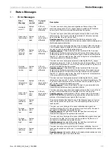
Page 37: ...ed joints are flame proofed o Enclosure and top cover of the electronic unit and the connection box o Casted cable glands reductions and sealing plugs at the electronic unit and the connection box o Threads at the probe and filter Repair of the flameproof joints is not prohibited 5 1 Exchange fuses Warning De energize the system first Abb 28 Position of the fuses fuse system voltage ampere nominal...

Page 38: ... SME 53 with integrated Pneumatics In the instrument air version in the Safe Area housing with an integrated pneumatic unit it is possible to adjust the reference and test air at the electronic unit In this respect the pump and instrument air versions are different In the pump version ambient air is used Only the flow rate of test air can be adjusted The instrument air version requires an external...

Page 39: ...he back of the electronic unit There are differences between the pump and the instrument air version In the pump version only the flow rate of test air can be adjusted In the instrumental air version both flow rates test air and reference air can be adjusted In systems with integrated pneumatics unit the flow rate of reference air can be seen in the menu Actual measured values Instrument air versi...

Page 40: ...ion of the V shield must be adjusted towards the flue gas flow Important Probes in the DustEx protection tube have a made of sintered metal which is welded to the flange of the filter 5 7 Replacing the probe Warning Hot Surface The probe may only be removed with heat insulated gloves Before removing the probe always switch off the supply voltage to the electronic system 1 Disconnect the wires at t...

Page 41: ...4 Probe connection box Insert the new inner part carefully into the probe and screw in the plate take care that the new inner part moves freely within the probe The probe inner part is now being pushed against the sensor by the spring Reconnect all electrical and pneumatic connections Connect the wires as follows Terminal Color Description Polarity Unit white brown signal wire measuring cell mV br...

Page 42: ...or 1 Filter Head 3b Sensor flange 2 Test gas distributor 4 Probe tube 3 O2 Sensor 5 Probe terminal box 3a Sensor flange seal 6 Probe inner part Take the probe out of the protection tube and wait until it has cooled down Dismantle the probe inner part Unscrew the filter head and dismantle the test gas distributor with guide tube by loosening the two allen screws Now remove the 4 Allen screws at the...

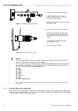
Page 43: ...Oe Sensor via the software SYS MENU System Configuration Set COe measurement OFF Switch off the power supply of the analyzer system Disconnect the COe sensor wires at the terminal block no 11 14 Figure 36 Connection of the COe sensor Unscrew and remove the cap nut Loosen the clamping ring the O ring and the retainer ring Pull the COe sensor out of the probe Take care The COe sensor may be hot Figu...

Page 44: ... entered to ensure correct measurement Failure to observe this information will destroy the COe sensor immediately The COe sensor must now be activated via the software SYS MENU System Configuration Set COe measurement ON After a COe sensor replacement the following values need to be entered as specified in the test certificate see paragraph 4 2 17 COe RH0 COe Offset COe Alpha COe Beta COe Gamma C...

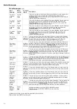
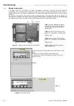
Page 45: ... X5 20A B Probe valve Normally open Triggering of the probe valve X5 24A B Limit value Normally closed Signals a violation of limit value 1 X5 21A B Limit value 2 Normally closed Signals a violation of limit value 2 X5 22A B Relay outputs and functions The relay system error is active also during the heating phase The relay contact for the probe valve is designed for max 230V and 1A Figure 40 Rela...

Page 46: ...eparate manual specification for the respective interface together with the shipment 5 16 Maintenance Intervals In general maintenance as well as the maintenance intervals always depends on the flue or process gas conditions in which the probe is installed Maintenance intervals may therefore vary between a few months up to a few years The biggest influencing factors are the presence of corrosive i...

Page 47: ...ow greater than 60 l h power supply too low flow rate too high and or temperature in the process too low electronic failure O2 probe temperature too high System error open 2 00 mA when not set differently The error can occur during measurement indicating that the O2 sensor temperature has risen 20 C 68 F above the set point temperature The O2 sensor heater is switched off An error reset can be car...

Page 48: ...COe sensor COe sensor heater short circuit 20 80mA unless set otherwise The error can occur at any time and signals a break in the circuit of COe sensor heater A reset can be carried out by the user once the fault has been remedied Possible causes contact problems between COe sensor cable and terminal points of the electronics respectively the probe probe cable is damaged defective COe sensor Open...

Page 49: ...ecified measurement tolerances are no longer guaranteed Electronic temp too high Possible Cause The ambient temperature of the transmitter is higher than the specified upper limit The specified measurement tolerances are no longer guaranteed Clock battery low The alarm can only be reset by the user after replacing the clock battery Lithium type 2032 As long as the system is connected to AC power t...

Page 50: ... reset by powering off the system and switching it back on The disturbances are signaled by red LEDs on the plate The green LED signals the error free operating condition Figure 41 Heater control unit Article No HCU 00001 LED 1 on Temp difference shutdown thermocouple may be broken Reset of the electronic unit by the reset button HEATER OFF LED 2 on Over temp shut down More than 810 C is measured ...

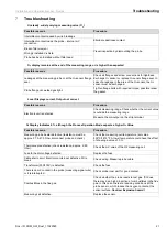
Page 51: ...ck measuring range Check whether the current value is outside the measuring range Measure the mA output on the strip terminal O2 Display Indicates 0 although the Process Operation Mode expects a higher O2 Value Possible reasons Procedure Measuring probe heater defective resistance must be approx 37 5 47 5 Ohm disconnect probe and check Check the measuring cell temperature set value 800 C 1472 F A ...

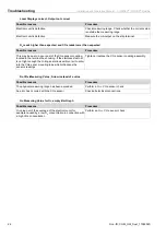
Page 52: ...ted in the terminal box housing If the stainless steel nut is not tight enough the O ring seal allows ambient air to enter into the COe senor mounting tube which influences the sensors readings Tighten or replace the COe sensor coupling assembly No COe Measuring Value Arrow instead of a value Possible reasons Procedure The physical measuring range has been exceeded Perform a O2 COe sensor check An...

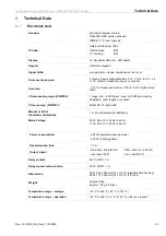
Page 53: ...g range COMTEC 1 range min 0 1000 ppm max 0 10000 ppm factory adjustable other ranges on request COe accuracy COMTEC better 5 of range end Manual or ACAL Automatic calibration 1 or 2 point automatic calibration Mains Voltage 230 V AC 10 50 Hz to 60 Hz 115 V AC 10 50 Hz to 60 Hz Power consumption 225 VA typical measuring mode 425 VA heating phase Recommended fuse 10 A Output signal O2 active 0 4 to...

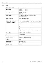
Page 54: ...n request Ambient temperature 20 C to 70 C 4 F to 158 F Maximum surface temperature depending on the ambient temperature Ambient temperature C Max surface temperature C 40 133 50 136 60 138 70 141 The given maximal surface temperatures 133 C to 141 C apply to the above mentioned ambient temperatures Reaction time 0 5 s process flow velocity 10m sec T90 5 0 s with testgas Probe material stainless s...

Page 55: ...ure 2 10 bar Flow rate continuously maximum 40 l h for reference air supply 180 l h during calibration Test gas test gas bottle for calibration system test Input pressure max 3 bar Specification test gas 1 optional 21 Vol O2 in N2 synthetic air in case instrument air is not available Specification test gas 2 The test gas used for calibration purposes must have the exact same composition as the tes...

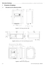
Page 56: ...l COMTEC OXITEC DustEx 26 Doc ID COM_OXI_Dust_11022020 B Dimension Drawings B 1 Dimensions of the Electronic Units Figure 43 Field housing sheet steel IP65 Figure 44 Electronic unit in 19 inch rack 4HE aluminium IP20 Figure 45 SME 56 GRP housing option ...

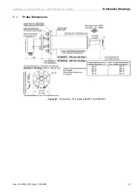
Page 57: ...Installation and Operation Manual COMTEC OXITEC DustEx Dimension Drawings Doc ID COM_OXI_Dust_11022020 27 B 2 Probe Dimensions Figure 46 Dimensions of the probes KES6001 and KES6002 ...

Page 58: ...on and Operation Manual COMTEC OXITEC DustEx 28 Doc ID COM_OXI_Dust_11022020 B 3 Counter Flange Dimensions Figure 47 Dimensions of counter flange ADP 6007 for KES600X Figure 48 Dimensions of counter flange ADP 6007 S01 for KES600X ...

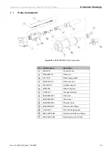
Page 59: ...ion box MSR 600X ST Probe tube FLD 1000 Probe flange gasket SIK 600X 2TH Probe inner part ZO2 60 0 1 1 O2 Measuring cell MZD 0005 Metal O ring seal 0 R 002311 Test gas distributor KES600080000 Filter head KES60000X000 COe Sensor KES600000X00 Protection tube KES6000000X0 Protection tube flange 0 R 000147 Prot tube flange gasket SMF 600STAUB Sintered metal filter and flange HRV 600STAUB Mounting rin...

Page 60: ...0 Figure 50 Gas plans Pressure control valve Filter Choke non return valve Choke non return valve Solenoid valve 3 2 ways Reference air pump Test air pump Solenoid valve 3 2 ways Solenoid valve 3 2 ways Flow meter Flow meter Instrument air in 4 10 Bar Reference air in Test gas in Max 3 Bar Test air in Test gas out 150 180 l h Test gas in Reference air out 30 40 l h Test gas out 150 180 l h Referen...

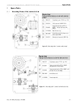
Page 61: ...tings 0 P 001508 Restrictor one way DFM 00001 Internal flow meter for reference air and test gas SME5 PLU 0025 Reference air pump for SME5 30l h Figure 51 Mounting plate 1 version with pumps Parts List Test gas and reference air unit for instrument air TRA 0017 Transformer primary 2 115V sec 115V PGM 0001 Test gas solenoid valve P01 for SME53 with pneumatic unit and fittings PGM 0002 Test gas sole...

Page 62: ...X10 0 L 000107 COe sensor board Rear side of mounting plate COMTEC only Info The spare parts used in SME54 19 racks are identical to the spare parts shown above C 2 Display Board Figure 54 Display board Parts List Display Board 0 L 000035 SME5 OXITEC display board without pneumatic 0 L 000036 SME5 OXITEC display board with pneumatic 0 L 000108 SME5 OXITEC display board CSP with pneumatic 0 L 00011...

Page 63: ...tions inadequate maintenance and non compliance with the operating instructions All ENOTEC products and systems which incorporate a heated sensor must be operated under continuous conditions If the heater power is switched off and on regularly the resultant thermal stress for the probe heater probe thermocouple and sensor will cause a shorter life span If it is not possible to operate the heated e...

Page 64: ...suing this declaration Manufacturer ENOTEC GmbH Höher Birken 6 51709 Marienheide Germany Tel 49 2264 45 78 0 Product model System OXITEC 5000 OXITEC Economy AQUATEC 1000 Electronic units SME 53 SME 54 Probe types KES 1000 KES 132X KES KIS 200X KES 500X Description InSitu oxygen analyzer system Relevant EC directives 2014 30 EU electromagnetic compatibility EMC 2014 35 EU low voltage directive 2014...

Page 65: ...llt gemäß den Bestimmungen der Richtlinien und durch Einhaltung der Normen Die Geräte sind mit folgenden Angaben gekennzeichnet EN 60079 0 2012 EN 60079 31 2014 The Essential and Safety Requirements are assured by compliance with the directive and observance of the normative documents The marking of the equipment includes the following 0158 II 2D Ex tb IIIC T133 C T141 C Db 20 C Ta 40 C 20 C Ta 70...

Page 66: ...nd Display 3 L Language settings 2 M Maintenance Intervals 16 Menu Explanations Time per test gas apply 2 Menu Overview 5 Mounting of the Probe 6 N Name Plate 6 P Position of the adjustment valves 9 Preparation of the pneumatic cable 8 Pressure and Flow rates 8 R Relay outputs 15 Replacing the COe Sensor 13 Replacing the Filter Head 10 Replacing the O2 Sensor 10 12 Replacing the probe 10 S Service...

Reviews: