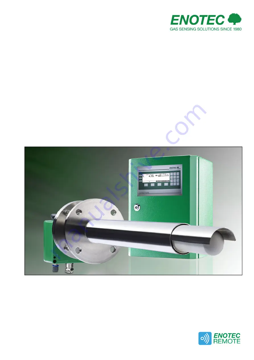
background image


Doc.-ID: OXI-11022020-EN 


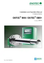
Installation and Operation Manual 

O

2

 Analyzer System 

OXITEC

®

 5000 / OXITEC

®

 5000+ 

Version 33 

for Software Version: 4.13 


Summary of Contents for OXITEC 5000 Series

Page 1: ...Doc ID OXI 11022020 EN Installation and Operation Manual O2 Analyzer System OXITEC 5000 OXITEC 5000 Version 33 for Software Version 4 13 ...

Page 2: ...e you with many years of trouble free operation with perfect measuring results Symbols used in this Manual All symbols listed beneath attached to the analyzer or noted in this manual show important information as well as safety instructions for installation operation and maintenance to protect the personnel and the equipment Warning Follow all instructions of this manual Consider Information Point...

Page 3: ...4 4 2 8 Automatic Calibration ACAL 24 4 2 9 Automatic Calibration Settings 24 4 2 10 ENOTEC REMOTE 25 4 2 11 Measuring units 25 4 2 12 Language 25 4 2 13 Change system code 25 4 2 14 Load factory settings 25 4 2 15 Service factory service settings 26 4 3 Calibration menu 26 4 3 1 Calibration menu display overview 26 4 3 2 1 point calibration manual 27 4 3 3 2 point calibration manual 27 4 4 System...

Page 4: ...probe without cooling tube for flue gas temperatures of up to 600 C Electronic unit SME 5 IP66 Safe Area max ambient temperature 20 C to 55 C 4 F to 131 F InSitu measuring probe IP65 Safe Area max ambient temperature 40 C to 80 C 4 F to 176 F Pneumatic cable Duct combustion chamber O2 probe signal cable Flue gas direction max flue gas temperature 600 C Solenoid valve optional Manufacturer supply C...

Page 5: ...Situ measuring probe IP65 Safe Area max ambient temperature 40 C to 80 C 4 F to 176 F Pneumatic cable Duct combustion chamber O2 probe signal cable Flue gas direction max flue gas temperature 1600 C Solenoid valve optional Customer supply Counter flange optional Manufacturer supply Isolation customer Space required 2 0 m for standard installation 0 8 m for 90 elbow construction Duct wall Power sup...

Page 6: ...bustible gases or in a location where combustible gases are present as the measuring cell temperature of 800 C could present an explosion hazard Info The minimum concentration of O2 in flue gas should under normal process conditions not be less than 0 5 If the O2 concentration is regularly below 0 5 we recommend the option of CSP Cell Surface Protection to protect the O2 sensor Caution Under no ci...

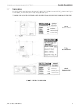
Page 7: ... line voltage the nominated current frequency protection class year of manufacture serial number order number and system order code The system order code refers to information which is detailed in the system test report and supplied with the system SME 53 Electronic Unit Probe Connection Box SME 54 Electronic Unit Figure 3 Position of the name plates ...

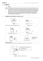
Page 8: ... are specified from 0 08 mm AWG 26 to 2 5 mm AWG 14 If wire end ferrules are used the next smaller size is required Before removal of the electronic terminal cover the line voltage must be switched off The line voltage to the electronic unit must be switched on again after the cover is back in position After installation power conducting parts may not be accessible 2 1 Installation requirements fo...

Page 9: ...pply cables Probe Cable FEP 0001 FEP 0004 armored version No Function Diameter Colors Additional info Measuring O2 sensor 2 x 0 75 mm 2 white brown brown with shield Thermocouple 2 x 0 75 mm 2 green white with shield Probe heating 3 x 1 5 mm 2 black blue green yellow Solenoid valve 2 x 0 75 mm 2 grey grey blue Figure 5 Probe cable FEP 0001 Caution The shield of the probe cable must only be connect...

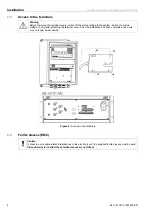
Page 10: ...ystem Switch the mains voltage on only after attaching the terminal cover After the installation has been completed live parts may no longer be accessible Figure 6 Access to the terminals 2 4 Ferrite sleeves EMC Caution In order to avoid cable related disturbances to the electronic unit the supplied ferrite sleeves must be used CE conformity is invalid if these ferrite sleeves are not fitted ...

Page 11: ...h 18 A B maintenance Grounding 19 A B system Error 4 PE protection earth 20 A B output A O2 measuring range 5 PE protection earth 21 A B O2 Limit Alarm 1 6 FE functional earth 22 A B O2 Limit Alarm 2 Shielding Probe solenoid valve Internal power supply probe heater 115V 23 A internal Power supply for probe solenoid valve 8 LH black 23 B 9 NH blue 24A LV grey 10 PE green yellow 24B NV grey blue O2 ...

Page 12: ...Installation Installation and Operation Manual OXITEC 5000 10 Doc ID OXI 11022020 EN 2 6 OXITEC 5000 Wiring diagram Figure 8 Wiring diagram of the OXITEC 5000 Analyzer system ...

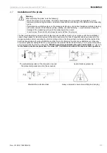
Page 13: ... all other process conditions must be in accordance with the specification Leave enough space for insertion removal of the probe and protection tube if supplied and ensure access to the measuring probe and or connecting box Before cutting a hole in the flue gas duct make sure that the inside of the duct has enough space for probe installation and that no soot is blown out nearby or any obstacles a...

Page 14: ...nting of the probe Figure 9 Mounting of the O2 probe for dimensions see section B Probe connection box Counter flange which has been welded gas tight at correct angle to duct Flange gasket Duct wall Protection tube Flue gas direction Flange gasket Insulate here to avoid dew point condensation ...

Page 15: ...nsation Gas entry Cooling tube flange Gas outlet do not block Minimum inside diameter of nozzle Ø 70mm Counter flange welded gas tight at correct angle 2 10 Adjusting the V shield Before installing the probe the direction of flue gas flow must be determined and the filter head assembly turned to such a position that the V shield faces the oncoming flue gas The filter head can be turned freely a fu...

Page 16: ...obe 1 mV O2 sensor white brown 2 mV O2 sensor brown 3 mV thermocouple 1 green 4 mV thermocouple 1 white 6 L 115 VAC heater black 7 N 115 VAC heater blue 8 PE protection earth green yellow 9 L 115 VAC solenoid valve grey 10 N115 VAC solenoid valve grey blue Figure 12 Electrical connections of the probe connection box 2 12 Requirements for Pneumatic Tube FEP 0002 Note the minimum bending radius FEP ...

Page 17: ...s 2 14 Gas plans Pneumatic version for Instrument air SME 50000010 Pneumatic version with pumps SME 50000020 Figure 14 Gas plans 1 Pressure control valve 1 Filter 2 Choke non return valve 2 Choke non return valve 3 Solenoid valve 3 2 ways 3 Reference air pump Test air pump 3a Solenoid valve 3 2 ways 4 Solenoid valve 3 2 ways 4 Flow meter 5 Flow meter A Instrument air in 4 10 Bar A1 Reference air i...

Page 18: ... Reference air B Test air 2 Solenoid valve 3 2 ways 3 Flow meter A1 Instrument air in A2 Test air in B Test gas in C Test gas out D Reference air out Figure 15 SME 50000080 gas plan for external pneumatics 2 15 Pneumatic Connections of the Probe 1 Reference air in FEP 0002 blue tube 2 Test gas in FEP 0002 green tube Figure 16 Pneumatic connections of the probe ...

Page 19: ...4 Reference air out Reference air out 1 4 Test air in Figure 17 Bottom view of SME 53 with pneumatic unit Instrument air version Pump version Figure 18 Back view of SME 54 19 4HE showing pneumatic connections Nr Tube Pump version Instrument air version 1 4 Testgas in Testgas in 1 4 Testgas out Testgas out 1 4 Reference air input Instrument air in 1 4 Reference air output Reference air out 1 4 Test...

Page 20: ...ts in use See section 0 Mounting of the Probe Do the conditions at site match the specification in the data sheets See section A Technical Data 3 2 System power up Switch on the line voltage to the system After a short power up information the user is prompted to Select language set the System date System time enter a TAG number and ENOTEC REMOTE code only if option ENOTEC REMOTE is factory activa...

Page 21: ... enabled back lit display Four softkeys with varying layout softkeys Numeric number bloc Figure 22 Keypad and display 3 6 Status LEDs 3 7 Softkey symbols Alarm orange is lit when an alarm has been activated e g O2 limit alarm Moves the selection one position upwards Moves the selection one position down wards Maint Orange a function has been accessed which may affect the measurement Leave an area ...

Page 22: ...ife Lambda Calibration results e g 2012 05 11 Choose date time Executed at Calibration method O2 sensor calibration Calibration results O2 value at test air 20 95 O2 calibrated to O2 O2 value at test gas O2 only if determined calibrated to O2 Calibration data O2 sensor offset mV O2 sensor slope mV dec only 2 point calibration Test gas data Test air 20 95 O2 Test gas e g 2 1 O2 Sensor raw data O2 v...

Page 23: ...mA mA output on system error mA O2 limit alarms O2 limit alarm 1 OFF ON at visible when set to ON hysteresis O2 limit alarm 2 OFF ON at visible when set to ON hysteresis O2 sensor calibration values O2 cal value offset mV O2 cal value slope mV dec Calibration settings Time per test gas apply Min Delay time to process Min Measurement value hold on calibration ON OFF Auto calibration ON OFF Calibrat...

Page 24: ...G number System date jjjj mm tt System time hh mm ss TAG ENOTEC REMOTE settings optional Visible when ENOTEC REMOTE interface is activated ENOTEC REMOTE ON OFF ENOTEC REMOTE code 8 digit code Visible when ENOTEC REMOTE is ON Range Short Medium Maximum Measuring units Temperature C F Pressure mbar psi Language Choose language Deutsch English Spanish Polish French Change system code Load factory set...

Page 25: ...y sets the duration for the continuous average measurement flowing average During a calibration or sensor verification the measurement average is not shown though still active for the analogue output 4 2 3 mA output on system errors The mA output value for a system error is specified in range of 0 3 55 mA or 20 41 to 20 80 mA The mA output value for a system error cannot be set in the mA measuring...

Page 26: ...lled calibration using the digital input of the O2 sensor The ACAL can be globally switched on or off and can only be started from the main screen of the display When a 2 point ACAL is set a test gas bottle must be permanently connected and turned on Info Make sure that the test air and test gas volume and flow settings needed for calibration are correct For systems with flow monitoring The flow r...

Page 27: ...ction the connection will fail In this case manually switch off the ENOTEC REMOTE and switch it back on again SYS MENU System configuration ENOTEC REMOTE Settings which will reset the module All previously paired users will need to delete their saved connection to the analyzer and re pair their devices 4 2 11 Measuring units Measuring units can be set for temperature C F and pressure mbar psi 4 2 ...

Page 28: ...st Gas apply The max adjustable measuring range Trend representation of measured O2 value and O2 target value The target value is determined by the O2 concentration in the test gas test air Time scale showing the elapsed time of the current calibration process The amount in seconds here 120 s refers to the end of the time scale Test Air apply The flow rate currently measured Current measured value...

Page 29: ...ue in Delay time to process if Meas Value hold on cal is set ON 10 Revert to main display 4 3 3 2 point calibration manual During the 2 point calibration of the sensor the calibration offset and slope is determined Hereby two gases are applied to the sensor test air and test gas In systems without integrated pneumatic units test gas needs to be applied manually and the flow control also may need t...

Page 30: ...Flow rate 3 bar max l h Source Process O2 sensor mV Flow rate l h Check mA outputs Set mA output 17A B mA Check relay outputs Relay contact at 18A B opened closed Relay contact at 19A B opened closed Relay contact at 20A B opened closed Relay contact at 21A B opened closed Relay contact at 22A B opened closed Check digital inputs Input status at 25A B Input status at 27A B Check mA inputs Check mA...

Page 31: ...C 1 0 A 250 V AC M L 5x20 mm F1 230 V AC 2 0 A 250 V AC T H 5x20 mm F1 115 V AC 4 0 A 250 V AC T H 5x20 mm F2 115 230 V AC 4 0 A 250 V AC M H 5x20 mm 5 2 Flow rates for Test Air and Reference Air The systems are factory set to the correct amounts of test air and or reference air The instrument air versions are designed for an inlet pressure of 1 10 bar With a higher inlet pressure of 6 bar it is n...

Page 32: ... and instrument air versions are different In the pump version ambient air is used Only the flow rate of test air can be adjusted The instrument air version requires an external supply of clean dry and oil free air instrument air Both flow rates test air and reference air can be adjusted In systems with integrated pneumatics unit the flow rate of reference air can be seen in the menu actual measur...

Page 33: ...an be adjusted at the back of the electronic unit There are differences between the pump and the instrument air version In the pump version only the flow rate of test air can be adjusted In the instrumental air version both flow rates test air and reference air can be adjusted In systems with integrated pneumatics unit the flow rate of reference air can be seen in the menu Actual measured values I...

Page 34: ... the holding screws Clamp the filter head in a vice Free the filter by using a hammer and a metal extension to force it from the filter head Figure 32 Remove old filter 5 6 2 Cement in new Filter Mix the supplied glue with water according to the instructions Spread the glue into the grooves of the seat and onto the filter part which comes into contact with the seat Push turn the filter into the se...

Page 35: ...ning Hot Surface The probe may only be removed with heat insulated gloves Before removing the probe always switch off the supply voltage to the electronic system After removal store the probe in a safe protected place and wait until it has cooled down below 35 C 95 F Note An exchange of the measuring cell is only necessary if the cell is leaking erratic or incorrect measured values Disconnect the ...

Page 36: ...spring tension Tighten the locking bolt and connect wires as follows Install the probe wait for the system to reach its operating temperature Carry out a O2 two point calibration after 24 hours of operation Protection cap Cell tube O2 sensor Ceramic rod Signal wire Flange gasket Thermocouple Probe tube Heater Screw M5 Figure 35 Construction of the O2 sensor holding tube Terminal Color Description ...

Page 37: ...on because this can be changed without dismounting the probe inner part as a whole Disconnect the wires in the connection box and loosen the 2 torx screws which hold the inner parts of the probe Pull off the thin transparent reference air pipe from the entry fitting at the connection box Pull out probe internal assembly carefully 4 hole ceramic rod with signal measuring wire thermocouple element a...

Page 38: ... Probe valve Normally open Triggering of the probe valve X5 24A B Limit value 1 Normally closed Signals a violation of limit value 1 X5 21A B Limit value 2 Normally closed Signals a violation of limit value 2 X5 22A B Relay outputs and functions The relay system error is active also during the heating phase The relay contact for the probe valve is designed for max 230 VAC and 1A Figure 37 Relay pl...

Page 39: ... manual specification for the respective interface together with the shipment 5 15 Maintenance Intervals In general maintenance as well as the maintenance intervals always depends on the flue or process gas conditions in which the probe is installed Maintenance intervals may therefore vary between a few months up to a few years The biggest influencing factors are the presence of corrosive ingredie...

Page 40: ...w greater than 60 l h power supply too low flow rate too high and or temperature in the process too low electronic failure O2 probe temperature too high System error open 2 00 mA when not set differently The error can occur during measurement indicating that the O2 sensor temperature has risen 20 C 68 F above the set point temperature The O2 sensor heater is switched off An error reset can be carr...

Page 41: ...ure System error open Circuit open or pressure transmitter signal less than 3 6 mA greater than 20 4 mA Error REMOTE module System error open Indicates a hardware error of the REMOTE module Possible cause the REMOTE module is defective Unlisted errors Other errors cannot be remedied by the customer Please contact a service point 6 2 Alarm Messages Error Message Relay contact Description Reference ...

Page 42: ...EC 5000 40 Doc ID OXI 11022020 EN 6 3 Maintenance Messages Maintenance message Relay contact Description Measured value s held Maint closed When measured values held is set to on the determined O2 mA output remains saved for a duration before a calibration ...

Page 43: ...ck measuring range Check whether the current value is outside the measuring range Measure the mA output on the strip terminal O2 Display Indicates 0 although the Process Operation Mode expects a higher O2 Value Possible reasons Procedure Measuring probe heater defective resistance must be approx 37 5 47 5 Ohm disconnect probe and check Check the measuring cell temperature set value 800 C 1472 F A ...

Page 44: ... request Accuracy 0 5 of measured value or 0 02 Vol O2 higher value valid Manual or ACAL Automatic calibration 1 or 2 point automatic calibration Mains Voltage 230 V AC 10 50 Hz to 60 Hz 115 V AC 10 50 Hz to 60 Hz Power consumption 400 VA heating phase 200 VA typical measuring mode Recommended fuse 10 A Output signal O2 active 0 4 mA to 20 mA max load 500 Ω galvanically isolated Relay contact 24 V...

Page 45: ...001 493 mm KES 2002 925 mm KES 2003 1839 mm KES 2004 2764 mm KES 2005 3689 mm KES 5001 508 mm KES 5002 939 mm KES 5003 1853 mm Insertion depth cooling tube 500 mm 1000 mm others on request Measuring principle zirconium oxide Process gas pressure 50 mbar 0 725 PSIG to atmospheric pressure Flue gas flow velocity 0 m s to 10 m s others on request Ambient temperature 40 C to 80 C 40 F to 176 F Reactio...

Page 46: ...e max 1 m Particle density max 1 mg m Oil content max 0 1 mg m Pressure dew point max 40 C or 10 C below lowest possible ambient temperature Constant 20 95 Vol O2 Input pressure 2 10 bar Flow rate continuously maximum 40 l h for reference air supply 180 l h during calibration Test gas test gas bottle for calibration system test Input pressure max 3 bar Specification test gas 1 optional 21 Vol O2 i...

Page 47: ...onal drawings Doc ID OXI 11022020 EN 45 B Dimensional drawings B 1 Dimensions of Electronic Unit Housing versions Figure 38 Dimensions in mm of the SME 53 Figure 39 Dimensions in mm of the SME 54 Figure 40 GRP protective housing optional Dimensions in mm ...

Page 48: ...ngs Installation and Operation Manual OXITEC 5000 46 Doc ID OXI 11022020 EN B 2 Probe Dimensions Figure 41 Dimensions of the KES 132X probes Figure 42 Dimensions in mm of the KES 132X probes with cooling protection tube ...

Page 49: ...ation and Operation Manual OXITEC 5000 Dimensional drawings Doc ID OXI 11022020 EN 47 Figure 43 Dimensions of the KES 200X probes Figure 44 Dimensions in mm of the KES 200X probes with cooling protection tube ...

Page 50: ...onal drawings Installation and Operation Manual OXITEC 5000 48 Doc ID OXI 11022020 EN Figure 45 Dimensions in mm of the KES 500X probes Figure 46 Dimensions of the KES 500X probes with cooling protection tube ...

Page 51: ...d Operation Manual OXITEC 5000 Dimensional drawings Doc ID OXI 11022020 EN 49 B 3 Counter Flange Dimensions Figure 47 Dimensions of counter flange ASR 1320 for KES 132X Figure 48 Dimensions of counter flange ADP 2000 ...

Page 52: ...Dimensional drawings Installation and Operation Manual OXITEC 5000 50 Doc ID OXI 11022020 EN Figure 49 Dimensions of counter flange ADP 2000 S02 ...

Page 53: ...Installation and Operation Manual OXITEC 5000 Dimensional drawings Doc ID OXI 11022020 EN 51 B 4 Dimensions of protection tube flanges Figure 50 Dimensions of protection tube flanges ...

Page 54: ...nts KES 132X Figure 51 KES 132X Probe Components No Part Part No 1 Connection Box ASK 1001 2 Measuring probe tube MSR 132X 2a Probe flange gasket FLD 132X 3 Probe inner part SIK 132X 4 Oxygen sensor ZO2 00 0 1 1 4a Measuring sensor gasket MZD 0001 5 Filter head KES 1320X00 6 Test gas valve Solenoid valve KES 13200X0 ...

Page 55: ...art No 1 Connection Box ASK 1001 2 Measuring probe tube MSR 200X 2a Probe flange gasket FLD 200X 2b Spacer 0 R 000476 3 Probe inner part SIK 200X 4 Oxygen measuring cell ZO2 00 0 1 1 4a Measuring cell gasket MZD 0001 5 Filter head KES 2000X000 6 Test gas valve Solenoid valve KES 20000X00 7 Protection Tube KES 200000X0 7a Protection tube flange gasket SRD 200X ...

Page 56: ...Connection Box ASK 1001 2 Measuring probe tube MSR 200X 2a Probe flange gasket FLD 200X 3 Probe inner part SIK 200X 4 Oxygen sensor cell ZO2 00 0 1 1 4a Measuring sensor gasket MZD 0001 5 Filter head KES5000X0000 6 Test gas valve Solenoid valve KES50000X000 7 Protection Tube KES500000X00 8 Protection tube flange KES5000000X0 8a Protection tube flange gasket A SRD 200X ...

Page 57: ...port tube HZH 00002 HZH 00002 HZH 00002 2 Heater HEI 132X HEI 2001 HEI 200X 3 Heater clamp 0 R 000474 0 R 000474 0 R 000474 4 Distance sleeve 0 R 000201 5 Ceramic rod KER 132X KER 2001 KER 200X 6 Tube clamp 0 R 000500 0 R 000500 0 R 000500 7 Spring 0 R 000044 0 R 000044 0 R 000044 8 Thermocouple MT2 132X MT2 2001 MT2 200X 9 Reference air hose RLS 0001 RLS 0001 RLS 0001 10 Signal wire MSD 132X MSD ...

Page 58: ...8 Restrictor one way DFM 0001 Internal flow meter for reference air and test gas SME 5 PLU 0025 Reference air pump for SME 5 30l h Figure 56 Mounting plate 1 version with pumps Parts List Test gas and reference air unit for instrument air TRA 0017 Transformer primary 2 115V sec 115V PGM 0001 Test gas solenoid valve P01 for SME 53 with pneumatic unit and fittings PGM 0002 Test gas solenoid valve P0...

Page 59: ...nce air and test air for version with internal pumps Figure 58 Mounting plate 2 Figure 59 Mounting plate 2 C 6 Display Board Parts List Display Board 0 L 000035 SME5 OXITEC display board without pneumatic 0 L 000036 SME5 OXITEC display board with pneumatic 0 L 000108 SME5 OXITEC display board with CSP with pneumatic 0 L 000110 SME5 OXITEC display board with RS232 with pneumatic Figure 60 Display b...

Page 60: ...nadequate maintenance and non compliance with the operating instructions All ENOTEC products and systems which incorporate a heated sensor must be operated under continuous conditions If the heater power is switched off and on regularly the resultant thermal stress for the probe heater probe thermocouple and sensor will cause a shorter life span If it is not possible to operate the heated equipmen...

Page 61: ...r ENOTEC GmbH Höher Birken 6 51709 Marienheide Germany Tel 49 2264 45 78 0 Product model System OXITEC 5000 OXITEC Economy AQUATEC 1000 Electronic units SME 53 SME 54 Probe types KES 1000 KES 132X KES KIS 200X KES 500X Description InSitu oxygen analyzer system Relevant EC directives 2014 30 EU electromagnetic compatibility EMC 2014 35 EU low voltage directive 2014 53 EU radio and telecommunication...

Page 62: ...errite Sleeves 8 I Installation Electronic Unit 6 Probe signal cable 7 L Language settings 25 M Maintenance Intervals 37 Measuring Principle 4 Mounting Plates of the Electronic Unit 56 N Name Plate 5 Name Plates 5 O OXITEC 5000 Wiring diagram 10 P Pneumatic Connections Probe 16 Position of the adjustment valves 31 Pressure and Flow rates 30 Probe Components 52 Probe inner parts 55 probe tube 34 R ...

Reviews: