background image

PEDESTAL INSTALLATION GUIDE

TESLA

®

 WALL CONNECTOR & CLIPPERCREEK HCS

A division of Enphase Energy, Inc. 

Summary of Contents for ClipperCreek TESLA

Page 1: ...PEDESTAL INSTALLATION GUIDE TESLA WALL CONNECTOR CLIPPERCREEK HCS A division of Enphase Energy Inc ...

Page 2: ...ments or instructions made in this document and disclaims any responsibility for such statements or instructions If you have questions about the use of this product contact your customer service representative Refer to the Customer Support section located in this guide TESLA Wall Connector Pedestal Installation Guide Version 3 March 2022 2022 Enphase Energy Inc All rights reserved Printed in the U...

Page 3: ...NSTRUCTIONS 4 INSTALLATION CONFIGURATIONS AND TOOLS REQUIRED 4 INSTALLATION REQUIREMENTS 8 9 PACKING LISTS 10 OPTIONAL ORDERABLE ITEMS 11 INSTALLATION CHAPTERS MAIN PEDESTAL 12 14 TESLA WALL CONNECTOR 15 21 CLIPPERCREEK HCS 22 25 CUSTOMER SUPPORT 26 WARRANTY INFORMATION 27 ...

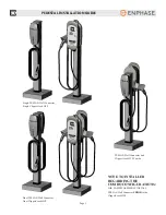
Page 4: ...l service provider anytime a procedural question arises DO NOT attempt to perform a procedure you are unsure of Read all installation instructions carefully before performing the pedestal and charging station installation EVSE PEDESTAL INSTALLATION GUIDE TESLA WALL CONNECTOR AND CLIPPERCREEK HCS CONFIGURATIONS Single TESLA Dual TESLA Single ClipperCreek HCS Dual ClipperCreek HCS Combo TESLA and Cl...

Page 5: ...ector Single ClipperCreek HCS TESLA Wall Connector and ClipperCreek HCS Combo Dual TESLA Wall Connector Dual ClipperCreek HCS NOTE TO INSTALLER REGARDING THE COMBO CONFIGURATIONS FOR EASIEST ASSEMBLY INSTALL TESLA Wall Connector PRIOR to the ClipperCreek HCS ...

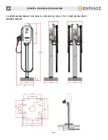
Page 6: ...Page 6 PEDESTAL INSTALLATION GUIDE TESLA WALL CONNECTOR SINGLE AND DUAL MOUNT CONFIGURATION DIMENSIONS ...

Page 7: ...Page 7 PEDESTAL INSTALLATION GUIDE CLIPPERCREEK HCS SINGLE AND DUAL MOUNT CONFIGURATION DIMENSIONS ...

Page 8: ...ing Plate Kit ClipperCreek part number 0300 00 021 Two 2 dedicated 208 or 240 VAC branch circuits Two 2 circuit breakers appropriately sized with respect to the charging capacity of each EVSE Two pairs 2x2 Live Line conductors one pair for each EVSE with enough length to comfortably pull all the way through and above the top of the pedestal Two 2 Ground Line conductors One for each EVSE or a singl...

Page 9: ...Anchor Bolts with Nuts and Washers REQUIRED EQUIPMENT FOR A DUAL MOUNT PEDESTAL WITH TWO CLIPPERCREEK HCS CHARGING STATIONS TWO EVSE S PER PEDESTAL One 1 ClipperCreek HCS EVSE Pedestal Kit ClipperCreek part number 0300 00 019 One 1 ClipperCreek Dual Mount HCS Pedestal Kit ClipperCreek part number 0300 00 020 Two 2 ClipperCreek HCS Charging Stations EVSEs part number depends on amperage selected Tw...

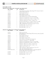
Page 10: ... 1 OD 0300 00 019 HCS PEDESTAL KIT STANDARD 4 FOOT SINGLE MOUNT PART NUMBER QTY DESCRIPTION 1001 0015 1 Holster gray polycarbonate 1003 0014 1 Pedestal Metalwork Cap with Rear Flange NOTE this item may already be attached to the top of the pedestal 1003 0023 2 Pedestal Metalwork Base Cover 1003 0035 1 Pedestal Metalwork 4 Foot Post 1003 0037 1 Pedestal Metalwork Hole Cover Plate 1003 0039 1 Pedest...

Page 11: ... Flat Head 1 4 20 Size 3 4 Length T27 Torx 4000 0012 2 Machine Screw Button Head 1 4 20 Size 1 Length T27 Torx 4000 0019 2 Machine Screw Button Head 1 4 20 Size 2 Length T27 Torx 4002 0001 2 Washer 8 Zinc 3 16 ID 7 16 OD 4002 0002 4 Washer Galvanized Steel Neoprene Bonded Seal 1 4 ID 5 8 OD 4002 0004 1 Washer Liquid Tight Sealing Thermoplastic 4013 0008 or 4013 0009 1 Pedestal Conduit Assembly Sta...

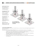
Page 12: ... behind the curb If a bumper block is in place the center of the pedestal base should be situated 12 behind the curb 2 ANCHOR BOLT PLACEMENT A minimum of four 4 anchor bolts must be embedded in the concrete pad for the purposes of securing the pedestal post The pedestal base is de signed to permit the anchor bolts to be arranged in many configurations including the following Use the Pedestal Base ...

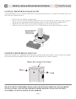
Page 13: ...hor bolts has been prepared and the three service conductors have been pulled through the underground conduit the pedestal post may be placed Feed the three service conductors up through the inside of the pedestal post The conductors must be of sufficient length to pass beyond the top of the pedestal so that final connections can be worked with comfortably at a later step Align the pedestal post b...

Page 14: ...ver piece are tucked inside of the opposite cover Align the four screw holes of each cover piece with the corresponding screw holes on the opposite cover Secure each cover piece to the other with four 4 6 32 x 3 8 flat head tapered screws using a 2 Philips head screwdriver 5 REMOVE THE PEDESTAL POST CAP A pedestal cap is provided to cover the opening to protect the conductors and inner pedestal fr...

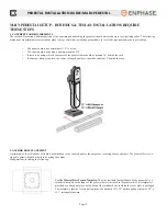
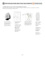
Page 15: ... inserts on the front of the pedestal post To properly position the Mounting Plate use a T27 Torx driver and two 2 1 4 20 x 3 4 Torx flat head tapered screws Begin with the top position first and tighten each of the 1 4 20 x 3 4 Torx flat head tapered screws about halfway in Firmly tighten both screws until the head of the screw is flush with the surface of the mounting plate For Dual Mount instal...

Page 16: ...mage the ribbon cable Disconnect the ground wire from the terminal block and push it out of the way to avoid damaging it when completing the next step Use a 1 32mm hole saw to remove the power entry knock out from the back of the connector CAUTION When using the hole saw be careful not to damage internal components Reconnect the Ground wire to the terminal block 3 PREPARE THE TESLA WALL CONNECTOR ...

Page 17: ...Align the TESLA Wall Connector over the Mounting Bracket Attach the grounding wire Fasten the TESLA Wall Connector onto the Mounting Bracket using the flange screws supplied with the TESLA Wall Connector and a ratchet wrench with 8mm socket to tighten firmly into position Use caution to prevent pinching wires For Dual Mount Installations repeat on the opposite side ...

Page 18: ... Turn off the Power WARNING RISK OF ELECTRIC SHOCK Before connecting the wiring use a volt meter to confirm that NO POWER is available at the service wiring or terminals Pull the service wiring into the TESLA Wall Connector Strip wires 3 8 10 mm Connect wiring to the terminal block Connect L1 to Black L2 N to Red and Ground to one of the two available Ground connectors as shown NOTE Maximum size o...

Page 19: ...ver the hinge located at the top of the connector NOTE Do not secure the front cover yet Turn on the Power Hold the RESET button for five seconds This button is located on the lower right side of the TESLA Wall Connector You should now hear the contacts close and see the lights sequentially illuminate green If the RED error light illuminates or flashes refer to the troubleshooting table in the TES...

Page 20: ...ble Doing so can damage the ribbon cable s connectors Adjust the dip switches to set the operating current based on the type of breaker being used Use a pointed non conductive object such as a plastic pen NOTE Power MUST be turned off before setting or changing DIP switches If you set DIP switches with the power on not only is it dangerous because of the risk of electric shock see warning above bu...

Page 21: ...ing slots Starting at the bottom and working upwards press firmly on both sides of the front cover until it clicks into place Using a T20 torx driver re attach the two security screws that you removed in STEP THREE Turn on the Power YOU HAVE NOW FINISHED INSTALLING THE TESLA WALL CONNECTOR ONTO THE PEDESTAL MOUNTING SYSTEM REFER TO THE TESLA WALL CONNECTOR INSTALLATION GUIDE FOR TROUBLESHOOTING AN...

Page 22: ...ening of the NPT Fitting is facing downward For Dual Mount Installations repeat on the opposite side 2 INSTALL THE WALL CONNECTOR MOUNTING PLATE A mounting plate is affixed to the front of the pedestal post to provide a flat and rigid base on which the ClipperCreek HCS can be mounted In the case of a Dual Mount Installation a second mounting plate is affixed to the opposite side of the pedestal po...

Page 23: ...e ninety degree NPT for connection Trim the EVSE conduit to length The recommended length to remain is 12 inches as measured from the bottom of the EVSE Route the three conductors that come through the EVSE s flexible conduit through the NPT connection and into the Pedestal Post No disassembly of the NPT Fitting is required Push the conduit onto the NPT Fitting ferrule and then tighten the domed s...

Page 24: ...o the pedestal with the two 2 1 4 20 x 1 Torx button head screws with washers using a T27 Torx driver 6 INSTALL THE COVER PLATE The cover plate is provided to cover the electrical access hole for Single Mount Pedestals only Skip this step if you are installing a Dual Mount Secure the cover plate to the Single Mount Pedestal using two 2 1 4 20 x 3 4 Torx flat head tapered screws using a T27 Torx dr...

Page 25: ...und the HCS Stow the Vehicle Connector in the holster The button does not need to be pressed simply insert until you hear the click to lock in place Verify the safety of the installation prior to turning on the circuit breaker Refer to the ClipperCreek HCS User s Guide for further operational and maintenance information YOU HAVE NOW FINISHED INSTALLING THE CLIPPERCREEK HCS ONTO THE PEDESTAL MOUNTI...

Page 26: ...d on the label If your call is made after business hours or on weekends please leave your name telephone number the unit serial number and a brief description of the problem A Service Representative will call back at the earliest opportunity TO CONTACT CLIPPERCREEK INC DIRECTLY FOR SERVICE CALL 877 694 4194 MONDAY THROUGH FRIDAY BETWEEN 8 00 AM AND 5 00 PM PACIFIC STANDARD TIME Visit us at www cli...

Page 27: ... use including but not limited to improper connections with peripherals external electrical faults accident disaster misuse abuse or modifications to the product not approved in writing by Enphase Any service repair outside the scope of this limited warranty shall be at applicable rates and terms then in effect This warranty covers factory parts and factory labor only it does not cover field servi...

Page 28: ...www clippercreek com 877 694 4194 ClipperCreek A division of Enphase Energy Inc ...

Reviews: