


Page 10
Copyright Enphase Energy Inc. 2011
141-00013 Rev 03b
Planning for Cable Lengths and Type
The Cabling System is flexible enough to adapt to almost any solar design. To
determine the length and cable type that you need, take into account the
following considerations:
The number of Enphase Microinverters to be installed on the AC
branch circuit
. Be certain to allocate the correct number of connectors,
including extra connectors for gaps and turns.
Additional length required to reach from the AC branch circuit
junction box to the first microinverter
. If greater than half a connector
interval is needed, it may be necessary to allow for one (or more) unused
connectors in order to span this distance. Unused connectors must be covered
with Enphase watertight sealing caps.
Additional length required to reach from one row of PV modules to the
next.
If the PV modules are laid out in multiple rows, the distance from one
row to the next often requires additional cabling length.
Bend radius
. When planning cabling turns or loops, you must account for a
minimum bend radius of 6.7 cm (2.625”).
Multiple sub-arrays
. Often, the AC branch circuit may be composed of
several smaller sub-arrays across more than one roof plane. In this case, the
cable is cut to service each smaller array, and the sub-arrays are connected
together using appropriately rated lengths of conduit. The transition from
cable to conduit is accomplished using an outdoor rated AC junction box, as
required by the NEC and local code. Unused connectors must be covered with
Enphase watertight sealing caps.
Mixture of PV modules in both portrait and landscape orientation
.
When PV modules are installed in mixed orientation (both portrait and
landscape orientation), there are three choices for cabling:
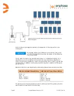
1.
Cabling with 1.025 meter spacing between connectors results in cleanest
install for the PV modules in portrait orientation. For PV modules placed in
landscape orientation, plan for an unused connector between each PV
module to accommodate the required additional distance. Unused
connectors must be covered with Enphase watertight sealing caps.
2.
Cabling with 1.7 meter spacing between connectors results in cleanest
install for PV modules in landscape orientation, but requires that any
additional cable length between PV modules in portrait orientation be
coiled and dressed so that cabling does not contact the roof. Again,
unused connectors must be covered with Enphase watertight sealing caps.
3.
Another solution when PV modules are installed in mixed orientation is to
transition between 1.025 and 1.7 meter spacing cable options using an
outdoor rated junction box. This junction box can be installed to the PV
racking.
Summary of Contents for ET10-208-30
Page 1: ...Installation Manual Enphase Engage Cable and Accessories ...
Page 4: ...Page 4 Copyright Enphase Energy Inc 2011 141 00013 Rev 03b ...
Page 6: ...Page 6 Copyright Enphase Energy Inc 2011 141 00013 Rev 03b ...
Page 24: ...Page 24 Copyright Enphase Energy Inc 2011 141 00013 Rev 03b ...
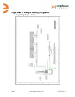
Page 26: ...Page 26 Copyright Enphase Energy Inc 2011 141 00013 Rev 03b Sample Wiring Diagram 208 Vac ...
Page 27: ......


