


Page 15
Copyright Enphase Energy Inc. 2011
141-00013 Rev 03b
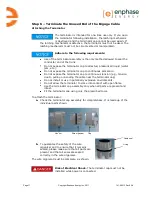
Step 5 – Dress the Engage Cable
Adhere to the following requirements:
Do not expose the connection to directed, pressurized liquid (water
jets, etc.).
Do not expose the connection to continuous immersion.
Do not expose the AC connector to
continuous tension (e.g., tension due to
pulling or bending the cable near the
connection)
Use only the connectors and cables provided.
Do not allow contamination or debris in the
connectors.
Use the cable and connectors only when all
parts are present and intact.
Fit the connection using only the prescribed
tools.
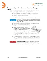
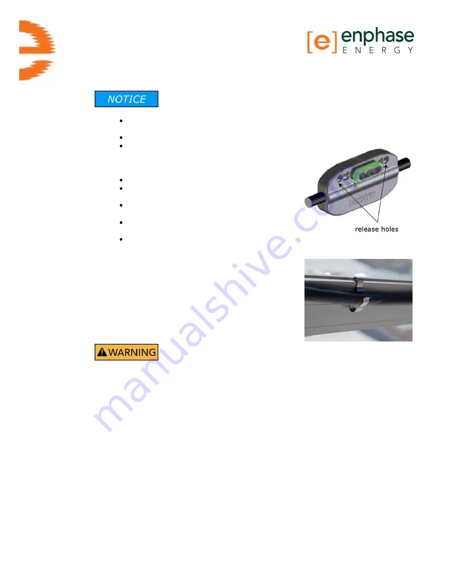
There are two release holes in the cable
connector. These holes are used to disconnect the connector.
Keep
these release holes clear and accessible.
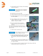
a.
Attach the Engage Cable to the rack using the
included clips, or you may use tie wraps.
The cable clips are designed so that the drop
cable from the microinverter can also be
dressed into the clip underneath the cable.
b.
Dress any excess cabling in loops so that
cabling does not contact the roof.
Tripping Hazard
. Do
not
leave the cabling to rest on the
roof. Loose cables might become a tripping hazard. Attach the
power cables correctly.
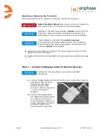
c.
Place tie wraps or clips on either side of the drop connector. Use one or
two additional clips, tie wraps, or other support scheme to secure the
cable between connectors.
d.
Remove the temporary shipping cap from the Engage Cable.
Summary of Contents for ET10-208-30
Page 1: ...Installation Manual Enphase Engage Cable and Accessories ...
Page 4: ...Page 4 Copyright Enphase Energy Inc 2011 141 00013 Rev 03b ...
Page 6: ...Page 6 Copyright Enphase Energy Inc 2011 141 00013 Rev 03b ...
Page 24: ...Page 24 Copyright Enphase Energy Inc 2011 141 00013 Rev 03b ...
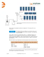
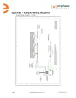
Page 26: ...Page 26 Copyright Enphase Energy Inc 2011 141 00013 Rev 03b Sample Wiring Diagram 208 Vac ...
Page 27: ......


