


Page 19
Copyright Enphase Energy Inc. 2011
141-00013 Rev 03b
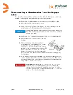
Replacing or Removing the Terminator
If the terminator must be replaced or removed, observe the following.
Risk of Electrical Shock.
Never open, remove or replace the
terminator while it is connected to the power supply.
Damage to the latching mechanism
cannot
be seen with the
naked eye. Label the opened terminator and dispose of it
immediately to ensure that it cannot be reused accidentally.
The terminator is intended for
one-time use
only
.
If you open the terminator again following the installation,
this will destroy the latching mechanism, meaning that the
unit then
cannot
be used again.
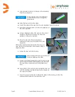
a.
Remove the terminator by cutting it off using a diagonal cutter set flush
against the end of the cable.
b.
Replace the terminator as described in the previous steps, beginning on page
17.
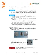
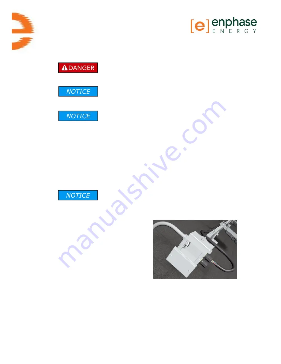
Step 7 – Connect the Engage Cable to Junction Box(es)
Perform the following steps in accordance with NEC
regulations.
a.
Connect Engage Cable into the AC branch circuit junction box using an
appropriate gland or strain
relief fitting. The cable
requires a strain relief
connector with an opening of
1.3 cm (0.5 inches) in
diameter.
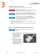
b.
Connect the Engage Cable
into additional junction boxes
as needed to transition to
conduit between smaller sub-
arrays. Remember to adhere
to branch limits for the
microinverters being used.
Summary of Contents for ET10-208-30
Page 1: ...Installation Manual Enphase Engage Cable and Accessories ...
Page 4: ...Page 4 Copyright Enphase Energy Inc 2011 141 00013 Rev 03b ...
Page 6: ...Page 6 Copyright Enphase Energy Inc 2011 141 00013 Rev 03b ...
Page 24: ...Page 24 Copyright Enphase Energy Inc 2011 141 00013 Rev 03b ...
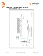
Page 26: ...Page 26 Copyright Enphase Energy Inc 2011 141 00013 Rev 03b Sample Wiring Diagram 208 Vac ...
Page 27: ......


