


Page 20
Copyright Enphase Energy Inc. 2011
141-00013 Rev 03b
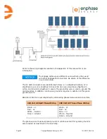
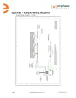
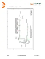
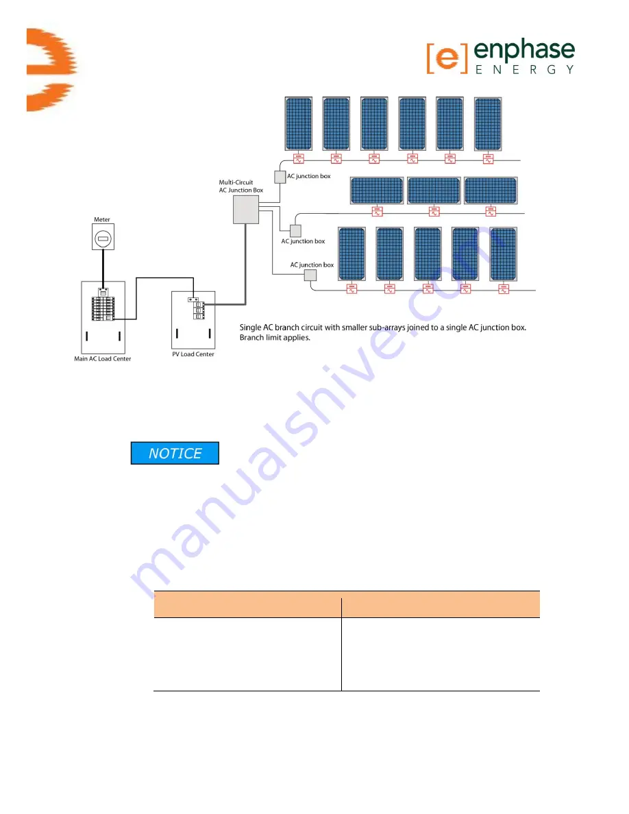
Refer to the wiring diagrams located in the Appendix of this manual for more
information.
The Engage Cable uses a different wiring scheme than used
with other Enphase Microinverters. Be aware of the difference
in wire color code.
The 12 AWG conductors are identified as follows: L1 is sheathed in Black, L2 is
sheathed in red, L3 is sheathed in blue (208 Vac only), Neutral is sheathed in
white, and Ground is sheathed in green. The grounding wire is used to ground the
microinverters. A WEEB or continuous ground is required in addition to this green
grounding wire.
Balanced 208 VAC is accomplished by alternating phases between microinverters.
240 Volt AC Split Phase Wiring
208 Volt AC Three-Phase Wiring
Black – L1
Red – L2
White – Neutral
Green - Ground
Black – L1
Red – L2
Blue – L3
White – Neutral
Green - Ground
The green wire acts as equipment ground. A continuous GEC for system ground is
also required as described in the next step.
Summary of Contents for ET10-208-30
Page 1: ...Installation Manual Enphase Engage Cable and Accessories ...
Page 4: ...Page 4 Copyright Enphase Energy Inc 2011 141 00013 Rev 03b ...
Page 6: ...Page 6 Copyright Enphase Energy Inc 2011 141 00013 Rev 03b ...
Page 24: ...Page 24 Copyright Enphase Energy Inc 2011 141 00013 Rev 03b ...
Page 26: ...Page 26 Copyright Enphase Energy Inc 2011 141 00013 Rev 03b Sample Wiring Diagram 208 Vac ...
Page 27: ......


