background image


IQ 6 / IQ 6+ Micro Installation and Operation 


© 2017 Enphase Energy Inc. All rights reserved. 

141-00034-01 


41 

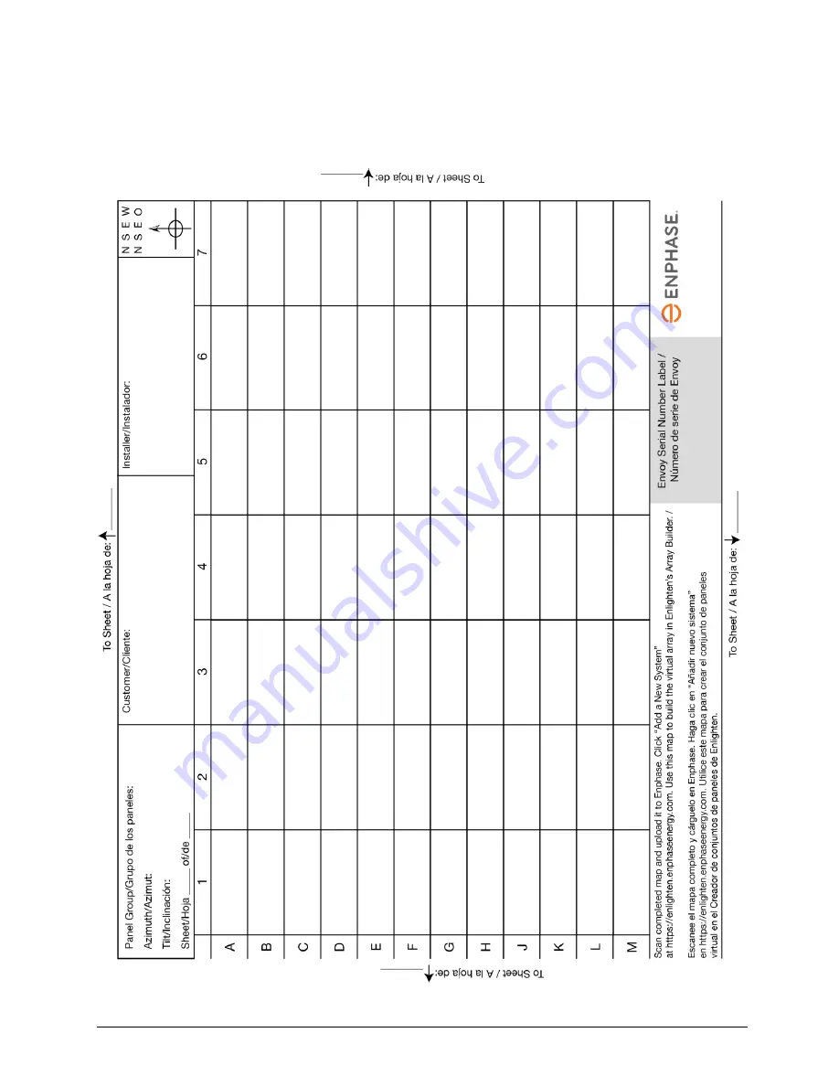
Enphase Installation Map 


Summary of Contents for IQ 6 Micros

Page 1: ...INSTALLATION AND OPERATION MANUAL December 27 2017 141 00034 01 Enphase IQ 6 and IQ 6 Micros ...

Page 2: ... to correct the interference by one or more of the following measures Reorient or relocate the receiving antenna Increase the separation between the equipment and the receiver Connect the equipment into an outlet on a circuit different from that to which the receiver is connected Consult the dealer or an experienced radio TV technician for help Changes or modifications not expressly approved by th...

Page 3: ... 15 Step 2 Position the Q Aggregator or Junction Box 15 Step 3 Mount the Microinverters 16 Step 4 Create an Installation Map 17 Step 5 Manage the Cabling 18 Step 6 Connect the Microinverters 18 Step 7 Terminate the Unused End of the Cable 19 Step 8 Complete Installation of Junction Box or an Enphase Q Aggregator 20 Step 9 Connect the PV Modules 20 Step 10 Energize the System 21 Set Up and Activate...

Page 4: ...hrough L H FRT and Must Trip Settings 33 SA11 Ramp Rate RR and Soft Start SS 33 SA12 Specified Power Factor SPF aka INV3 33 SA13 Volt VAr Mode VV 33 SA14 Frequency Watt FW 34 SA15 Volt Watt VW 34 Specifications 35 IQ6 60 2 US Microinverter Specifications 35 IQ6PLUS 72 2 US Microinverter Specifications 38 Q Cable Specifications 40 Enphase Connector Ratings 40 Enphase Installation Map 41 Sample Wiri...

Page 5: ...ty instructions DANGER This indicates a hazardous situation which if not avoided will result in death or serious injury WARNING This indicates a situation where failure to follow instructions may be a safety hazard or cause equipment malfunction Use extreme caution and follow instructions carefully WARNING This indicates a situation where failure to follow instructions may result in burn injury NO...

Page 6: ...ing with microinverters DANGER Risk of fire The DC conductors of the PV module must be labeled PV Wire or PV Cable when paired with the Enphase Microinverter DANGER Risk of electric shock Risk of fire Only qualified personnel may connect the Enphase Microinverter to the utility grid Do not attempt to repair the Enphase Microinverter it contains no user serviceable parts If it fails contact Enphase...

Page 7: ...ially explosive environments Do not allow the terminator to come into contact with open flame Fit the terminator cap using only the prescribed tools and in the prescribed manner Use the terminator to seal the conductor end of the Enphase Q Cable no other method is allowed PV Rapid Shutdown Equipment PVRSE This product is UL Listed as PV Rapid Shut Down Equipment and conforms with NEC 2014 and NEC ...

Page 8: ...phase Installer Toolkit mobile app for iOS and Android devices It allows installers to configure the system while onsite eliminating the need for a laptop and improving installation efficiency You can use the app to o Connect to the IQ Envoy over a wireless network for faster system setup and verification o View and email a summary report that confirms a successful installation o Scan device seria...

Page 9: ...n through a broadband router or modem the Enphase IQ Microinverters automatically begin reporting to Enlighten Enlighten presents current and historical system performance trends and informs you of PV system status Optimal Reliability Microinverter systems are inherently more reliable than traditional inverters The distributed nature of a microinverter system ensures that there is no single point ...

Page 10: ...patible with PV modules as listed in the following table For specifications see Technical Data on page 30 of this manual You can refer to the Enphase Compatibility Calculator at enphase com en us support module compatibility to verify PV module electrical compatibility To ensure mechanical compatibility be sure to order the correct connector type for both microinverter and PV module from your dist...

Page 11: ... minimize voltage rise Select the correct wire size based on the distance from the beginning of the microinverter AC branch circuit to the breaker in the load center Enphase recommends a voltage rise total of less than 2 for the sections from the microinverter AC branch circuit to the breaker in the load center Enphase provides guidance about choosing wire size and maximum conductor lengths in the...

Page 12: ... a lightning and or surge suppression device In addition to having some level of surge suppression it is also important to have insurance that protects against lightning and electrical surges Enphase has tested the devices in the following tables Residential Commercial Citel DS72 RS 120 surge protector data sheet Delta LA 302 lightning arrestor website Midnite solar surge protection device MNSPD 3...

Page 13: ...progress To download go to enphase com toolkit or scan the QR code at right Tie wraps or Q Cable Clips Q CLIP 100 Enphase Sealing caps Q SEAL 10 for any unused drops on the Enphase Q Cable Enphase Terminator Q TERM 10 typically two needed per branch circuit Enphase Disconnect Tool Q DISC 10 Enphase Q Aggregator Q BA 3 1P 60 single phase for multiple branch circuits optional Enphase Q Commercial Ag...

Page 14: ...hase Q Cable Step 2 Position the Q Aggregator or Junction Box Step 3 Mount the Microinverters Step 4 Create an Installation Map Step 5 Manage the Cabling Step 6 Connect the Microinverters Step 7 Terminate the Unused End of the Cable Step 8 Complete Installation of Junction Box or an Enphase Q Aggregator Step 9 Connect the PV Modules Step 10 Energize the System Enphase Q Aggregator Enphase IQ 6 or ...

Page 15: ...meet your planned needs WARNING When transitioning between rows secure the cable to the rail to prevent cable damage or connector damage Do not count on connector to withstand tension Step 2 Position the Q Aggregator or Junction Box A Verify that AC voltage at the site is within range Service Type and Voltage L1 L2 240 V Split Phase 211 to 264 VAC 208 V Single Phase 183 to 229 VAC B Install an Enp...

Page 16: ... 3 cm 1 2 between the back of the PV module and the top of the microinverter WARNING Install the microinverter under the PV module to avoid direct exposure to rain UV and other harmful weather events Do not mount the microinverter upside down B Torque the microinverter fasteners as follows Do not over torque 6 mm mounting hardware 5 N m 45 to 50 in lbs 8 mm 5 16 mounting hardware 9 N m 80 to 85 in...

Page 17: ...abels from the microinverter mounting plates and placing the labels on the map You will also place the Enphase IQ Envoy and IQ Battery serial number on the map after installation After you have created the installation map use the Enphase Installer Toolkit mobile app to record serial numbers and configure the system For Installer Toolkit details refer to Detect the Microinverters in the help topic...

Page 18: ...es can become a tripping hazard Dress the Enphase Q Cable to minimize this potential Step 6 Connect the Microinverters A Connect the microinverter Listen for a click as the connectors engage B Cover any unused connector with Enphase Sealing Caps Listen for a click as the connectors engage WARNING Risk of electric shock Risk of fire Install sealing caps on all unused AC connectors as these connecto...

Page 19: ... into the slot on top of the terminator to hold it in place and use a torque wrench or channel lock pliers to tighten the hex nut until the threads disappear Torque to 7 Nm E Hold the terminator body stationary with the screwdriver and turn only the hex nut to prevent the conductors from twisting out of the separator NOTE Hold the terminator body stationary with the screw driver and turn only the ...

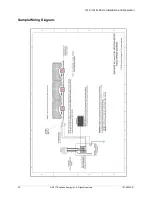
Page 20: ...grounding B Refer to the wiring diagrams on page 42 for more information Wire colors are listed in the following table Wire Colors L1 Black L2 Red Step 9 Connect the PV Modules WARNING Electrical shock hazard The DC conductors of this photovoltaic system are ungrounded and may be energized A Connect the DC leads of each PV module to the DC input connectors of the corresponding microinverter B Chec...

Page 21: ... reset see DC Resistance Low Power Off Condition on page 22 Set Up and Activate Monitoring Refer to the Enphase IQ Envoy Quick Install Guide to install the IQ Envoy and set up system monitoring and grid management functions This guide leads you through the following Connecting the Envoy Detect devices Connecting to Enlighten Registering the system Building the virtual array NOTE When the utility r...

Page 22: ...ntil the error has been cleared An insulation resistance IR sensor in the microinverter measures the resistance between the positive and negative PV inputs to ground If either resistance drops below a threshold the microinverter stops power production and raises this condition This may indicate defective module insulation defective wiring or connectors moisture ingress or a similar problem Althoug...

Page 23: ...d time for this microinverter and is still pending Method 2 Use Installer Toolkit to Clear the Condition On the list of detected microinverters a green dot or red square appears to the left of each microinverter serial number A green dot indicates Status OK A red square indicates an event for that microinverter Tap the to the left of the serial number to view details for a microinverter event If t...

Page 24: ...208 Volt AC Single Phase L1 to L2 183 to 229 VAC L1 L2 to ground 106 to 132 VAC E Using an Enphase disconnect tool disconnect the AC cable for the microinverter in question from the Enphase Q Cable F Verify that utility power is present at the microinverter by measuring line to line and line to ground at the Enphase Q Cable connector G Visually check that the AC branch circuit connections Enphase ...

Page 25: ...n us support contact If Enphase authorizes a replacement follow the steps below To ensure the microinverter is not disconnected from the PV modules under load follow the disconnection steps in the order shown A De energize the AC branch circuit breaker B Enphase AC connectors are tool removable only To disconnect the microinverter from the Enphase Q Cable insert the disconnect tool and remove the ...

Page 26: ...que the mounting fasteners to the values shown Do not over torque 6 mm 1 4 mounting hardware 5 N m 45 to 50 in lbs 8 mm 5 16 mounting hardware 9 N m 80 to 85 in lbs When using UL 2703 mounting hardware use the manufacturer s recommended torque value D If you are using bonding hardware the old bonding hardware should be discarded and new bonding hardware must be used when installing the replacement...

Page 27: ...ning is inhibited on the IQ Envoy you must use the Installer Toolkit scanning tool to provision them on the IQ Envoy rather than using the IQ Envoy s device scanning function to discover them If this is not possible and you need to enable device scanning on the IQ Envoy contact Enphase Customer Support at enphase com en us support contact b Method 2 Use an IQ Envoy Press the Device Scan button on ...

Page 28: ...ort Connector Spacing Options Q Cable is available in three connector spacing options The gap between connectors on the cable can be 1 3 meters 2 0 meters or 2 3 meters The 1 3 meter spacing is best suited for connecting PV modules installed in portrait orientation while the 2 0 meter and 2 3 meter spacing allows you to install 60 cell and 72 cell PV modules in landscape orientation respectively C...

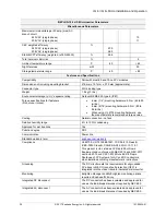
Page 29: ...h circuit of 35A that can be installed on a 40A max OCPD Field wireable connectors male Q CONN 10M Make connections from any Q Aggregator open connector or Field Wireable female connector Field wireable connectors female Q CONN 10F Make connections from any Q Cable open connector or Field Wireable male connector Cable clips Q CLIP 100 Used to fasten cabling to the racking or to secure looped cabli...

Page 30: ...aximum input voltage of the Enphase Microinverter PV modules must have conductors labeled PV Wire or PV Cable to comply with NEC for Ungrounded PV Power Systems Verify that the voltage and current specifications of the PV module match those of the microinverter The maximum short circuit current rating of the PV module must be equal to or less than the maximum input DC short circuit current rating ...

Page 31: ... installer following the requirements of the local electrical utility is allowed to make Grid Profile adjustments NOTE Grid profile changes are applied only after a microinverter is detected In some regions and in some situations microinverter trip points may be adjusted to account for high grid voltage or for local conditions Grid profile management tasks include Set the grid profile for your reg...

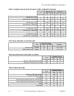
Page 32: ...itude percentage 119 104 119 104 High voltage 1 time s 299 800 0 800 300 0 1 0 High voltage 1 magnitude percentage 115 102 115 102 Nominal operating range percentage 110 88 110 88 Low voltage 1 time s 299 800 0 300 300 0 0 5 Low voltage 1 magnitude percentage 98 70 98 70 Low voltage 2 time s 149 800 0 000 150 0 0 2 Low voltage 2 magnitude percentage 96 50 96 50 Low voltage 3 time s 29 800 0 000 30...

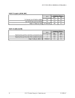
Page 33: ...A NA 0 5 0 1 Low frequency 2 magnitude Hz NA NA 59 9 50 SA11 Ramp Rate RR and Soft Start SS Units Adjustment Range Tolerance Max Min Ramp up rate Irated s 100 1 3 I rated Soft start ramp rate Irated s 100 0 11 3 I rated SA12 Specified Power Factor SPF aka INV3 Units Adjustment Range Max Min Inductive under excited power factor VAr W 0 7 1 0 Capacitive overexcited power factor VAr W 1 0 0 7 SA13 Vo...

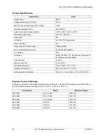
Page 34: ...requency with function enabled Hz 57 65 High end frequency droop settings Hz 62 60 1 Slope of frequency droop Prated Hz 200 20 SA15 Volt Watt VW Units Adjustment Range Max Min Adjustment range of the start of the curtailment function V 130 0 121 0 Adjustment range of the stop of the curtailment function V 138 0 123 0 Slope of voltage curtailment Prated V 83 5 5 ...

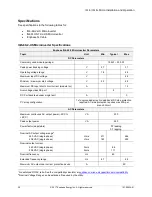
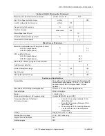
Page 35: ...lass DC port II DC Port backfeed under single fault A 0 PV array configuration 1x1 ungrounded array No additional DC side protection required AC side protection requires max 20A per branch circuit AC Parameters Maximum continuous AC output power 40 C to 65 C VA 230 Peak output power VA 240 Power factor adjustable 0 7 leading 0 7 lagging Nominal AC output voltage range2 240 VAC single phase 208 VAC...

Page 36: ...ef EN 50530 99 5 Total harmonic distortion 5 Ambient temperature range C 40 65 Night tare loss mW 50 Storage temperature range C 40 85 Features and Specifications Compatibility Pairs with most 60 cell PV modules the PV module DC conductors must be labeled PV Wire or PV Cable to be compliant with NEC for Ungrounded PV Power Systems Dimensions not including mounting bracket 219 mm x 191 mm x 37 9mm ...

Page 37: ... PV Systems for AC and DC conductors when installed according manufacturer s instructions Grounding The DC circuit meets the requirements for ungrounded PV arrays in NEC Ground fault protection GFP is integrated into the class II double insulated microinverter Monitoring Enlighten Manager and MyEnlighten monitoring options require an Enphase IQ Envoy Communication Power line Integrated DC disconne...

Page 38: ...red AC side protection requires max 20 A per branch circuit AC Parameters Maximum continuous AC output power 40 to 65 C VA 280 Peak output power VA 290 Power factor adjustable 0 7 leading 0 7 lagging Nominal AC output voltage range 240 VAC single phase 208 VAC single phase Vrms Vrms 211 183 240 264 229 Nominal output current 240 VAC single phase 208 VAC single phase Arms Arms 1 17 1 35 Nominal fre...

Page 39: ...bs When using UL 2703 mounting hardware use the manufacturer s recommended torque value Cooling Natural convection no fans Relative humidity range 4 to 100 condensing Approved for wet locations Yes Pollution degree PD3 Communication Power line Standard warranty term enphase com warranty Compliance UL62109 UL1741 IEEE1547 FCC Part 15 Class B ICES 0003 Class B CAN CSA C22 2 NO 107 1 01 This product ...

Page 40: ...on rating IEC 60529 IP67 NEMA 6 UV resistance 720h Compliance RoHS OIL RES I CE UV Resistant combined UL for Canada and United States Conductor size 12 AWG Maximum loop size 12 cm 4 75 Flat cable dimensions 6 mm x 9 5 mm 0 2 x 0 37 Sealing cap dimensions 38 6 mm x 20 mm 1 5 x 0 7 Cable connector dimensions 20 mm x 1 1 mm x 6 5 mm 0 7 x 0 04 x 0 25 Enphase Connector Ratings Enphase connectors in th...

Page 41: ...IQ 6 IQ 6 Micro Installation and Operation 2017 Enphase Energy Inc All rights reserved 141 00034 01 41 Enphase Installation Map ...

Page 42: ...IQ 6 IQ 6 Micro Installation and Operation 2017 Enphase Energy Inc All rights reserved 141 00034 01 42 Sample Wiring Diagram ...

Reviews: