2
Warning! Risk of electric shock.
To maintain the warranty,
do not modify the cover.
Wire the Grid Connections
A ) Use conductors sized per local code requirements taking into con-
sideration the voltage drop/rise and upstream breaker or fuse. The
terminals accept wire range 1/0 to 250kcmil. Wires must be Class B
or Class C only, and conductors with finer strands are not approved.
Note that the rated maximum breaker size is 250 A.
B ) The terminal lugs on the left with four terminals are for the grid
connection. Install L1 into the left-most terminal, L2 into the second
from the left, L3 into the third from left and neutral at the remaining
terminal. These connections require a 7/16 Allen wrench.
C ) Connect the ground to a ground lug. Ground connections requite
a 5/16 Allen wrench.
D ) Torque all connections as indicated by the
Wiring Table
.
4
Wire Inputs from the Array (AC Branch Circuits)
A ) Use copper conductors sized to meet local code requirements and
voltage drop/rise considerations. The terminals accept wire range 1/0
to 250kcmil. Wires must be Class B or Class C only, and conductors
with finer strands are not approved.
B ) Connect the ground (green or green/yellow) to a ground lug. Ground
connections require a 5/16 Allen wrench, and accept a wire range of 4
to 2/0 AWG.
C ) The terminal lugs on the contactor (on the right side of the box)
with three terminals are for the array connection. Install L1 into the
left-most terminal, L2 into the center, and L3 into the right. These
connections require a 7/16 Allen wrench.
D ) Connect the Array neutral, if required, to the terminal block shared with
the Grid connections.
E ) Torque connections as indicated by the
Wiring Table
.
NOTE
:
Enphase IQ Series Microinverters use a two-wire system and
do not use a Neutral. However, the IQ Envoy in the NPR still requires a
Neutral from the load center.
Warning! Risk of equipment damage.
Observe bend radius
requirements when routing wires.
WIRING TABLE
Grid/Array Connection
Torque
250kcmil - 3/0
275 lbs•in.
2/0 - #6
120 lbs•in.
Copper conductors only, rated minimum 90°C. Follow
NFPA 70 (NEC) or CSA C22.1 part 1 and all local
codes.
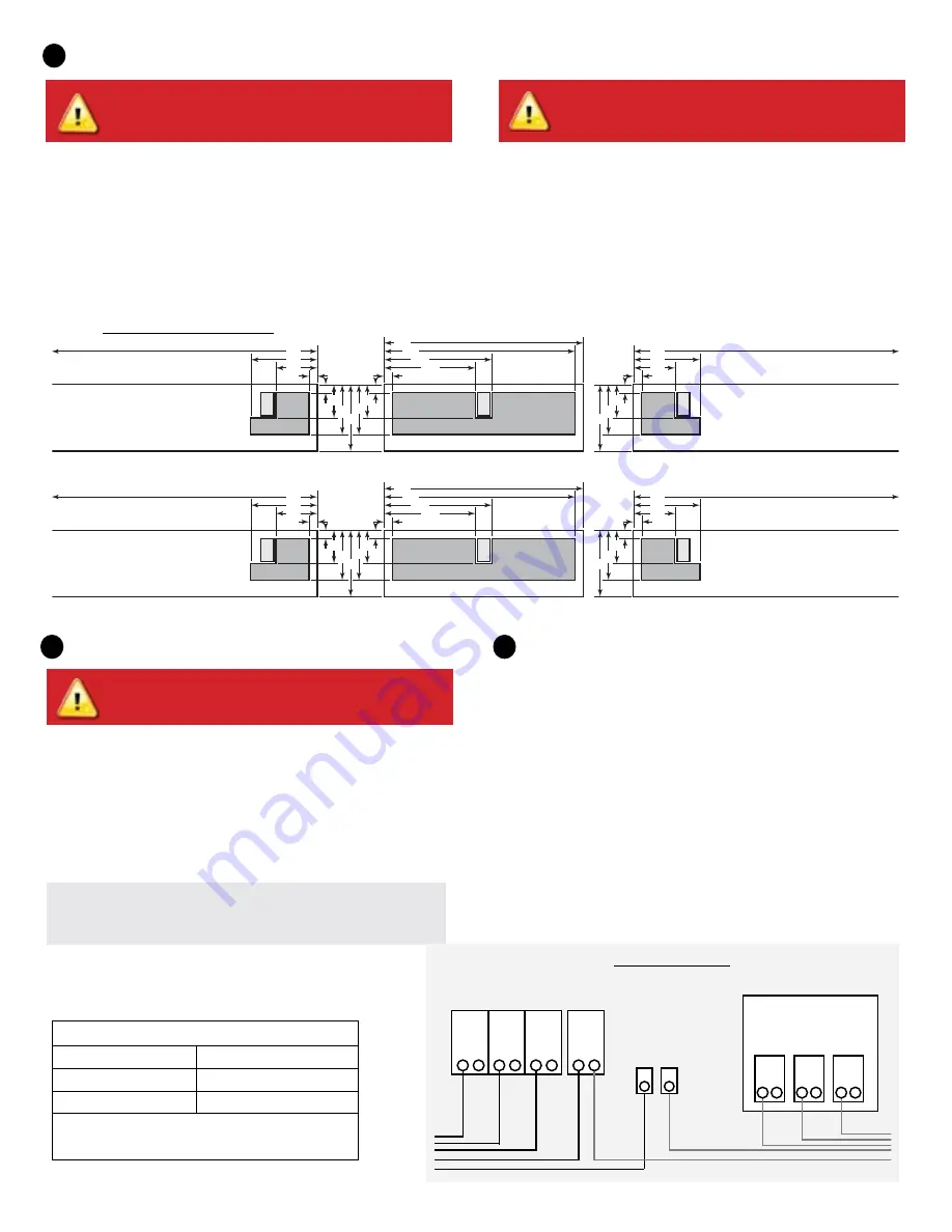
Drill Holes to Accept Conduit
A ) Unlock and open the Three-Phase NPR cover.
B ) See the Conduit Entry diagram for the best locations to drill holes for conduit fittings.
NOTE: When drilling, consider the internal parts of the NPR. Make sure that the holes do not interfere with the internal workings, mechanics, or the cover
legs in the corners of the NPR.
Best Practice:
Use a stepped drill bit to make the conduit holes. Using a hole saw may crack the plastic housing. As an alternative, use a sharp chassis
punch with caution.
C ) Use a snap punch or other type of center punch to prevent the drill from wandering. Drill a pilot hole with a smaller drill before using a step drill bit.
D ) Use only UL-listed rain-tight hubs for wire entry into the enclosure.
3
Warning! Risk of equipment damage.
Do not drill conduit
holes on the top of the box or at any location that allows
moisture ingress.
1”
1”
23”
13”
11”
6”
4”
4”
8”
8”
24”
Conduit Entry
Location Bottom
Side
Conduit
Entry
Right
Side
1”
4.5”
8”
6”
30”
1”
4.5”
8”
30”
Conduit
Entry
Left
Side
Top
Back
1”
4”
6” 1”
25.4
25.4
584
330
279
152
102
102
203
203
610
Conduit Entry
Location Bottom
Side
Conduit
Entry
Right
Side
25.4
114
203
152
762
25.4
114
203
762
Conduit
Entry
Left
Side
Top
Back
25.4
102
152 25.4
Inches
mm
GRID
Contactor
L1
L2
L3
N
L1
L2
L3
GRID/
ARRAY
ARRAY
GND
Black
Red
Blue
W
hit
e
W
hit
e
Black
Red
Blue
Gr
n/Y
ello
w
Gr
n/Y
ello
w
Conduit entry diagram
Wiring diagram


