background image


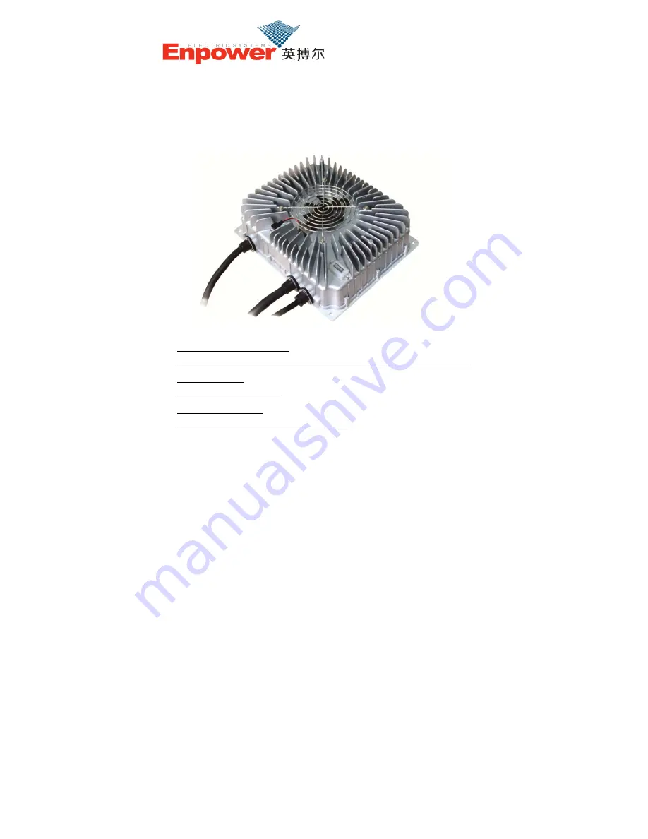
CH4100 Series High Efficiency Intelligent Charger 

User Manual Ver.2.1


Kevin Yan 

Tel & Fax: +86 21 54381028 

Add: Room 209, Building 6, No 15 Chunshen road 1985, Minhang District, 

Shanghai, China 

E-mail: kevin@xineyi.com 

Skype: kevinyan.xinyi 

www.xineyi.cn; http://xineyi.en.alibaba.com; 

Summary of Contents for CH4100 Series

Page 1: ...lligent Charger User Manual Ver 2 1 Kevin Yan Tel Fax 86 21 54381028 Add Room 209 Building 6 No 15 Chunshen road 1985 Minhang District Shanghai China E mail kevin xineyi com Skype kevinyan xinyi www xineyi cn http xineyi en alibaba com ...

Page 2: ...oney saving to use the charger is designed according to IP66 protection grade and achieved high waterproof performance Another feature includes small size light weight quiet operation beautiful appearance simple installation operation and maintenance and so on The charger adopts microcomputer measurement and control technology embedded CPU can accurately detect various states of battery Advanced m...

Page 3: ...s to prevent the cables from becoming too hot when charging so to prevent fires 3 Please do not disassemble the charger this may cause electric shock or other injuries 4 If the charger need to be connected to AC power supply with extension cables please make sure that the extension cable can withstand the maximum input current GB 2 5mm2 copper core cable is recommended to be used and limit the ext...

Page 4: ... it will damage the charger or batteries 12 Do not pull twist or shake the cables to avoid damage to the charger s cables and connection terminals If the cable is worn please replace it immediately III Preventing Leakage and Fire 1 Correct use of Breakers Sockets and Cables 1 Its required to use a leakage protection air breaker with leakage protection function 2 Its required to use reliable qualif...

Page 5: ...or flame retardant sheath or shells of breakers plugs and sockets and so on 2 Correct Use of Input Connections 1 It s required to use a dedicated 16A power plug for the charger 2 It s required to use copper core cables with flame retardant sheath the cables core diameter is not less than 2 5mm2 3 Make sure that the plug is clean no dirty and no damage before charging 3 Charging Environment Require...

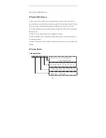
Page 6: ...arly using the test button to ensure its protection function is valid 3 Make sure to use a dedicated input cable and plug for the charger 4 Make sure that there are no foreign matters between the charger s shell and the cooling fan to avoid damage to the fan 5 Make sure that the appearance of battery is not ballooning the battery is not overheating when charging IV Product Models 1 Naming Rules CH...

Page 7: ...ructure code B such as CH4100 4825B V Technical Specifications Rated input voltage 220Vac 50 60Hz Input voltage range 85 265Vac Note When the Input voltage is lower than 185Vac the output power will be limited to 1 5KW Input Current 15A 220Vac input full power output Power Factor 0 99 220Vac input full power output Total Harmonic Current 5 220Vac input full power output Nominal output voltage Un S...

Page 8: ...king temperature 25 55 Note models whose output power greater than 2KW will ensure 2KW output at 60 Storage temperature 40 85 Recognition certificates CE VI parts list A AC input Cables B DC output cables C Signal Cables D Charging indicator E Mounting plate F Shell G Cooling fan and fan cover A B C E F G D ...

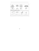
Page 9: ...r matching DJ7031 4 8 21 Needle No Wire Color Wire core diameter Description 1 brown 2 5 mm2 L Live wire 2 blue 2 5 mm2 N Neutral wire 3 Yellow and green 2 5 mm2 PE Protective grounding wire Output Cables Terminal Model SB50 Needle No Wire Color Wire core diameter Description red 6 mm2 Output positive pole black 6 mm2 Output negative pole ...

Page 10: ...11 3 yellow 4 purple DJ7021 1 5 21 Battery Temperature sensor interface DJ7021 1 5 11 5 white 6 pink DJ7043 2 21 Serial communication interface DJ7043 2 11 7 Greenyellow 8 Whiteblue 9 Whitegreen 10 orange DJ7021 2 11 Forbidden signal interface normal close DJ7021 2 21 11 grey Wire core diameter 0 5 mm2 for all Signal wires Signal Cables Terminal Diagram ...

Page 11: ... 10 Direction of view form the cables to terminal DJ7031Y 2 3 11 DJ7021 1 5 11 DJ7043 2 11 DJ7021 2 21 ...

Page 12: ...of working conditions of the charger with different color combinations The following table is a description of indicator information LED Indicator Information Description I Charging Process Information 1 Low battery power R 2 Battery charge lower than 80 R 3 Battery charge between 80 90 Y 4 Battery charge between 90 100 G 5 Full charge Normal process of charging continuous Green light Battery temp...

Page 13: ...verheating or ballooning during charging process you should stop the charger immediately by unplug the plug from the AC socket 6 Pre Charge timeout R G Y Y Y Y Y 7 Internal temperature sensor fault R G Y Y Y Y Y Y 8 Output voltage feedback fault R G Y Y Y Y Y Y Y 9 Low temperature start delay When the internal temperature of charger is between 20 to 30 C the charger will delay starting for 1 2 min...

Page 14: ...t 50mm away from cooling fan of the charger to other obstructions to improve heat radiating of the charger as shown in Figure If cables of the charger need to be bended the length from bending place to the shell should not be less than 50 mm as shown in Figure ...

Page 15: ... recharge Check whether cooling fan is fault or air vents are obstructed Input fault protection Poor contact of charger s input side Charger is broken If no poor contact phenomenon occurs please contact us Charging timeout Battery is damaged or aging Check and replace battery Battery Overheating Battery is damaged or aging Check and replace battery Pre charge timeout Battery is damaged or aging Ch...

Page 16: ...e battery Charger overheating protection Check if there are foreign matters around the fan and remove them Check whether the cooling fan is working correctly or contact us to replace the fan LED indicator lights but no charging Connectors are not connected firmly or the polarity is reversed Battery is disconnected Connect all connectors correctly and recharge Battery is broken Replace new battery ...

Page 17: ...ndition that all operations are according to user s manual we will replace or repair free of charge 2 Warranty period and maintenance mode From date of purchase within 12 month free of charge to repair Users need to pay for reparation beyond warranty period 3 If faults happen within warranty period in follow cases cost of material and service need be paid appropriately A Guarantee paper does not h...

Reviews: