background image


28 

 Installation instruction 

for flat collectors on flat roof or foundation. 


Note! 

Due to high temperatures in the solar system is necessary to use vents made completely out 
of metal. 


6.3.5 Connection of the clamping plugs – for meander collectors 

Mount the clamping plugs on the sub pipes that are not used for supply and return. (on the 
diagonal of the collector or the battery): 
 
1 – clamping plug 
2 – solar collector  
 
- strengthening sleeve is pre-installed in the sub pipe, 
- place the clamping nut on a connection pipe, 
- place the clamping ring on a connection pipe, 
- place the clamping plung on a connection pipe 
- screw the clamping nut on a clamping plug. 


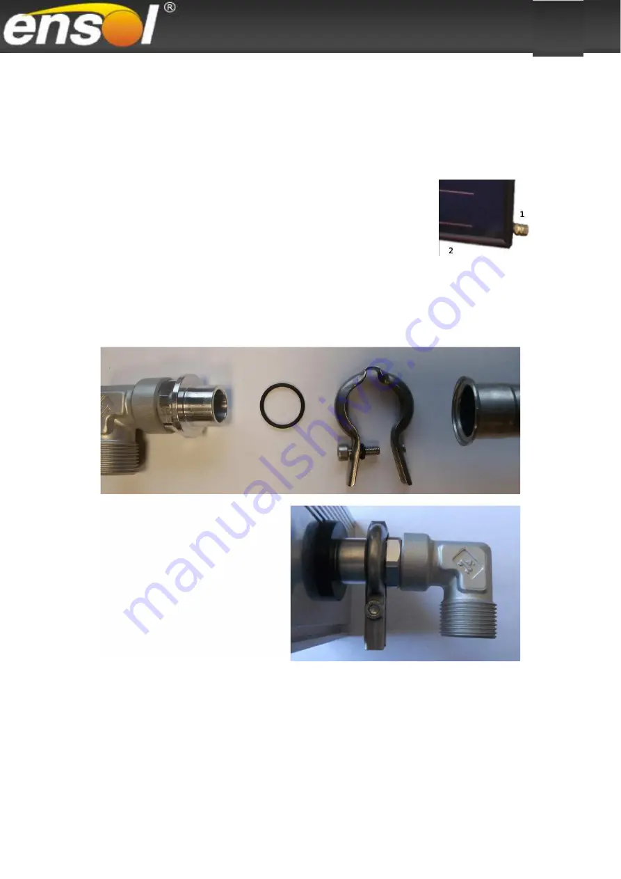
6.4 Mounting an o-ring connecting system 


6.4.1 Connecting elements mounting instruction 


-  at  the  end  of  connecting  elements  one  piece  of  o-ring  (end  cap,  elbow,  compensator) 
should be placed, 
- a connecting system element with o-ring should be placed inside of a collecting pipe, 
- then the clamp in the place of the collar should be put and tightened  with an attached bolt. 


Summary of Contents for EM2V/2.0

Page 1: ...Installation instruction For flat solar collectors on flat roof or foundation Installation instruction for flat solar collectors on flat roof or foundation 01 2019 Read before installation ...

Page 2: ...p 2 20 75 105 ES2V 2 0 HE vertical meander Cu Cu 1006 2007 85 38 2 02 clamp 1 80 60 90 ES2V 2 0 AL vertical meander Al Al 1006 2007 85 38 2 02 o ring v 1 1 80 40 60 EM2V 2 0 Al Cu vertical meander Al Cu 1006 1988 85 38 2 0 clamp 1 80 60 90 EM2V 2 0 vertical meander Cu Cu 1006 1988 85 38 2 0 clamp 1 80 60 90 EM1V 2 0 Al Cu vertical double harp Al Cu 1006 1988 85 40 2 0 clamp 1 80 60 90 EM1V 2 0 ver...

Page 3: ...fety and proper positioning of the collectors on the roof as well as the proper execution of the hydraulic connection The drawings and the information included in the instruction apply to a vertical and horizontal installation of collectors The installation of collectors described in the instruction may only be performed by qualified persons who have expertise in a range of gas and water installat...

Page 4: ...owing unloading instructions Read the instruction before proceeding to unloading of the vertical collector pallet 1 The first stage before unloading is to set the transport pallet on a flat surface Figure 1 1 shows the transport pallet set on a flat consolidated foundation 2 The second stage of unloading is to put a 30mm high board under the transport pallet so that the inclined transport pallet b...

Page 5: ...g 3 1 The delivery completeness Before installation it is necessary to check if the delivery is complete see figure below and the delivered components are not damaged in case of discovering any damages of element or part the replacement of a such should be immediately provided the replacement must be provided only with the application of original spare parts ...

Page 6: ...6 Installation instruction for flat collectors on flat roof or foundation 3 1 1 Installation set for vertical collectors 3 1 2 Installation set for horizontal collectors ...

Page 7: ... 2 1120 4 2240 6 2240 2 1120 6 2240 8 2240 2 1120 8 2240 10 2240 4 2 Vertical collectors 2 65m2 Multi slot section l 2460 pc 2 1230 2 2460 2 1230 2 2460 4 2460 2 1230 4 2440 6 2460 2 1230 6 2460 8 2460 2 1230 8 2460 10 2460 4 3 Horizontal collectors 2 65m2 Multi slot section l 2500 pc 2 2500 4 2500 6 2500 8 2500 10 2500 12 2500 14 2500 16 2500 18 2500 20 2500 5 Fastening holder UM114 pc 2 4 6 8 10...

Page 8: ...pc 0 2 4 4 6 5 1 Vertical collectors 2 0m2 Multi slot section l 2240 pc 2 1120 2 2240 2 1120 2 2240 4 2240 2 1120 4 2240 5 2 Horizontal collectors 2 65m2 Multi slot section l 2460 pc 2 1220 2 2440 2 1220 2 2440 4 2440 2 1220 4 2440 5 3 Horizontal collectors 2 65m2 Multi slot section l 2500 pc 2 2500 4 2500 6 2500 8 2500 10 2500 6 Fastening holder UM114 pc 2 4 6 8 10 7 Mounting bolt set 1 Set 4 8 1...

Page 9: ...ersion economical without inclination angle adjustment and bottom strut positioning spacing of the triangle feet The collation applies to the part of the instruction only for installation of collectors with the surface of 2 0m2 on supporting structure on a roof or flat surface in light version which is an additional version ...

Page 10: ...12 4 Multi slot section Collector 2 65m2 lm 2 1 23 2 2 46 2 2 46 2 1 23 4 2 46 4 2 46 2 1 23 5 Multi slot section connector pc 2 2 4 65 Side fastening plate PMB35 pc 4 4 4 4 4 7 Inter collector fastening plate PMM112 pc 2 4 6 8 8 Tee head bolt set 1 set 4 6 8 10 12 Tee head bolt INOX M8x20 Nut INOX M8 Resilient plate INOX M8 Plate INOX M8 9 Mounting bolt set 2 set 4 6 8 10 12 tee head bolt INOX M8...

Page 11: ...or 2 65m2 lm 2 1 23 2 2 46 2 2 46 2 1 23 4 2 46 4 2 46 2 1 23 5 Multi slot section connector pc 2 2 4 6 Side fastening plate PMB35 pc 4 4 4 4 4 7 Inter collector fastening plate PMM112 pc 2 2 8 Inter collector fastening plate PMM79 pc 2 4 4 6 9 Tee head bolt set 1 set 4 6 8 10 12 Tee head bolt INOX M8x20 Nut INOX M8 Resilient plate INOX M8 Plate INOX M8 10 Mounting bolt set 2 set 4 6 8 10 12 tee h...

Page 12: ... 9 The delivery completeness for clamp connecting system on a pipe union for double harp collector Connecting system for double harp collectors Battery x No Name unit 1 2 3 4 5 1 Elbow fi22 x GZ3 4 pc 1 1 1 1 1 2 Pipe union fi22 x fi22 pc 0 1 2 2 3 3 Compensator fi22 x fi22 pc 0 0 0 1 1 4 Cross fitting fi22 x GZ3 4 with a vent pc 1 1 1 1 1 In case of a battery with 4 and 5 collectors the compensat...

Page 13: ... a vent pc 1 1 1 1 1 5 Clamping end cap fi22 pc 2 2 2 2 2 In case of a battery with 4 and 5 collectors the compensator needs to be placed between 2nd and 3rd collector 3 1 12 The delivery completeness for o ring v 1 connecting system on compensator for meandric collector horizontal installation Connecting system for meandric collectors Battery x No Name unit 1 2 3 4 5 6 7 8 9 10 1 Clamping end cap...

Page 14: ...20 3 1 13 The delivery completeness for o ring v 1 connecting system on compensator for meandric collector Al Al vertical installation Connecting system for meandric collectors Battery x No Name unit 1 2 3 4 5 1 End cap o ring v 1 pc 2 2 2 2 2 2 Elbow o ring v 1 pc 1 1 1 1 1 3 Compensator o ring v 1 pc 0 2 4 6 8 4 Cross fitting with a vent o ring v 1 pc 1 1 1 1 1 5 Gasket o ring v 1 pc 4 8 12 16 2...

Page 15: ...a solar controller installation instruction hot water tank 3 4 Tools and additional equipment level gauge harness with a safety cable for work at heights scaffolding a roof ladder or a crane 3 5 Collector location Potential quantity of the absorber radiation depends on a proper location of the absorber in relations to incident rays Collector surface horizontal position to radiation is an optimum m...

Page 16: ...ce to seawater e g Mirosol TS 4 Supporting construction installation 4 1 Inclination angle of the collectors 4 1 1 Roof or flat surface In case of collector installation on a roof or a flat surface the inclination angle of an installing system corresponds directly to the assumed inclination of collectors 4 1 2 Roof or surface of inclination angle up to 20 In case of roofs inclined in the southern ...

Page 17: ...rmined as 30 45 and 60 depending on the position of the installation set In order to obtain the assumed inclination angle it is necessary to connect properly the sections of the installation set 30o angle is obtained by connecting the holes A1 with B1 and B2 with C1 45o angle is obtained by connecting the holes A2 with B1 and B3 with C1 60o angle is obtained by connecting the holes A2 with B1 and ...

Page 18: ...18 Installation instruction for flat collectors on flat roof or foundation 4 3 The installation set construction on a flat roof or a foundation ...

Page 19: ... the base of the installation set All of the triangles are assembled in the same manner Note Before a supporting triangle assembly all of the components should be laid out according to the figure presented below When of all the components are arranged the assembly triangle can be bolted together bearing in mind the setting of a suitable inclination angle 4 2 Determining the inclination angle of th...

Page 20: ... of supporting triangles and struts light version economical The supporting triangles are the base for an installation set All of the triangles are assembled in the same manner The installation distance between each triangle should be set accordingly with the dimensions shown in the figure The struts are bolted to the assembled triangles ADDITIONAL OPTION Note Before a supporting triangle assembly...

Page 21: ...upporting triangle more Spacing between the supporting triangles depends on the quantity of the installed collectors and is respectively as follows Standard version Light version 4 7 Number and configuration of multi slot sections The installation set includes an adequate number of multi slot sections depending on the quantity of collectors in a set Assembly triangles are provided with holes for i...

Page 22: ...with each other in accordance with the table of configurations according to the figure presented below Note In order to avoid an uncontrolled displacement of a connector screws can be used as distance elements screws are not delivered with the set The connector itself is not assembled screw the screws into the profiles at a distance of x about 55mm from the edge using the supplied connecting eleme...

Page 23: ...w Fastening holder should be attached to the wider edge of the multi slot section 4 12 Fastening the structure to the surface After assembly the supporting structure should be put in its place of destination The supporting structure should be fixed to the surface with anchor bolts to prevent it from being torn out of the surface Via the holes in the foot of the supporting structure the places wher...

Page 24: ...stallation on a supporting structure for on Compensator set During a collector installation it is necessary to abide by all safety Note Note During transport and installation the collectors need to have fall protection There are four fasteners for each collector two per one section Place the bolts in the sections two per each collector Place the collector on the multi slot sections in such way tha...

Page 25: ...ouble ones between the collectors PMB35 PMM112 PMM79 In the place of pipe union an inter collector fastening plate PMM79 should be placed it sets the distance between the collectors 67mm In the place of the compensator comes an inter collector fastening plate PMM112 which sets the distance between the collectors 100mm In case of an installation of a battery of 4 or 5 collectors the compensator sho...

Page 26: ...connectedto one battery 6 3 1 Collector connection with a clamping compensator Double harp collectors connection of upper connectors Meandric collectors connection of lower and upper connectors 1 connection pipe 2 strengthening sleeve 3 compensator nut 4 clamping ring 5 compensator core Place the compensator on the first collectors connector then move the second collector closer and bolt the compe...

Page 27: ... insulated flexible hose in the connection pipe 1 there is a pre installed strengthening sleeve 2 place the clamping nut 3 on the connection pipe 1 place the clamping ring 4 on the connection pipe 1 place the immersion sleeve with the complete cross fitting 5 on the connection pipe 1 screw the clamping nut 3 on the cross fitting 5 on the left side place the silicone gasket 6 in the insulated flexi...

Page 28: ...llector strengthening sleeve is pre installed in the sub pipe place the clamping nut on a connection pipe place the clamping ring on a connection pipe place the clamping plung on a connection pipe screw the clamping nut on a clamping plug 6 4 Mounting an o ring connecting system 6 4 1 Connecting elements mounting instruction at the end of connecting elements one piece of o ring end cap elbow compe...

Page 29: ...spring from slipping 6 6 Temperature sensor installation in a hybrid collector Installation instruction for temperature sensor the sensor should be placed in a specially placed sleeve mounted under a Ø22mm pipe not in the transverse joint as in flat collectors after placing the sensor in the sleeve about 26cm the sensor cable should be stabilized with a bolt 6 7 Connection of collecting pipes Hydr...

Page 30: ...pen the drain valve 3 and 4 and start the pump Close the ball valve 5 causing liquid flow through the solar collectors During filling and venting the system you should open and close the ball valve 5 several times Do not turn off the pump until the system will be completely vented that is until the air bubbles cease to flow out of the transfer hose 2 Open the ball valve 5 and close the drain valve...

Page 31: ...mage by birds For insulation inside a building use insulation resistant to high temperatures 7 5 Masking profile installation additional element Masking profile installation instruction Masking profile 1 is installed between collectors 2 by the means of three mounting elements 3 By the means of mounting bolt 4 fix the mounting elements 3 to the masking profile 1 Placing the mounting elements two p...

Page 32: ...ion check the solar fluid resistance to frost by the means of a control device refractometer In case of a significant decrease of resistance of fluid against freezing it is necessary to replace it and vent the whole system once again System pressure working pressure in the solar system needs to be monitored After the start up period no pressure drop is allowed Expansion vessel input pressure of an...

Reviews: