background image


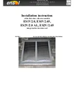
Installation instruction  

of the flat solar collectors models ES1V2.0, ES1V2.65,  

ES2V/2.0 AL, ES2V/2.65 

 integrated in the slate roof.   


3.5  Location of a collector 


Potential quantity of the absorbed radiation depends on a proper location of 


the absorber in relation to falling sunbeams.  


Optimum is a perpendicular position of a collector surface in relation to the 


falling solar radiation.   


Recommended location of a collector: 


inclination angle: 


40 – 45

for a year-long installation,  


approximately 30

o

 for installations used in summer,  


approximately 60

o

 for installations used in winter, 


positioning of a collector in the southern direction (or approximate to the 


southern direction).  


Solar collectors must not be installed at the inclination below 30

o

 or  


over 75

o

.  


It is recommended to install the collectors on the southern roof slope. During 


the installation work particular attention should be paid to protect the  


collectors from being overturned by strong winds. Permissible snow  


and wind load amounts to max. 2,0 kN/m². 


Collectors field should be located in such a way that the absorber will  


not be shadowed by the adjacent buildings, trees, etc.  


In case of a larger number of collector fields it is important that the front row 


of the collectors do not shadow the back one.   


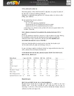
3.6 Technical data for the flat collector models: ES1V/2.0,  ES1V/2.65,  
ES2V/2.0 AL, ES2V/2.65 


Flat collector   

Symbol  ES1V/2.0 

ES2V/2.0 AL   ES1V/2.65 

ES2V/2.65 

Unit      

Width     

1006 

1006 

1120 

1120 

mm 

Height   

2007 

2007 

2356 

2356 

mm 

Depth 

85 

85 

85 

85 

mm 

Collector weight 

40 

40 

49 

49 

kg 

Area  

2,02 

2,02 

2,65 

2,65 

m

Connectors: Cu pipe 

Φ


22 

22 

22 

22 

mm 

Fluid volume  

1.8 

1.8 

2.2 

2.2 

dm

Max working pressure  

p

max 

6.0 

6.0 

6.0 

6.0 

bar 

Optimum flow min. - max.   m 

60-90 

40-60 

75-105 

75-105 

dm

3

/h 


Required space  


ES1V/2,0 and ES2V/2,0 AL for vertical installation  
Required  about  2400  mm  in  height  and  1800  mm  in  width  for  the  first 
collector  and  +  1110  mm  in  width  for  each  consecutive  one.  In  case  of 
mounting  a  collector  on  the  inclined  roof  the  minimum  distance  between 
collectors and the roof edge is 1m.  
 

Summary of Contents for ES1V2.0

Page 1: ...els ES1V2 0 ES1V2 65 ES2V 2 0 AL ES2V 2 65 integrated in the slate roof Installation instruction of the flat solar collectors models ES1V2 0 ES1V2 65 ES2V 2 0 AL ES2V 2 65 integrated in the slate roof...

Page 2: ...ncing the installation work it is necessary to immediately get acquainted with the safety tips 2 1 Notes included in the instruction The installation instruction includes important information concern...

Page 3: ...d against weather conditions 3 2 Technical Documentation Solar installation set consists of different components Before installing any of the components you should become familiar with an adequate ins...

Page 4: ...flashing 1 1 Support frame for centre flashing 1 1 Cover flashing left 1 Cover flashing right 1 Cover flashing 1 Wind protection rail 2 1 Collector bracket 4 2 Collector clamping 40 x 40mm 4 Linear co...

Page 5: ...overturned by strong winds Permissible snow and wind load amounts to max 2 0 kN m Collectors field should be located in such a way that the absorber will not be shadowed by the adjacent buildings tre...

Page 6: ...proofed by the plumber any leaks are associated with getting air into the solar thermal system with maximize the risk of corrosion Once air get into the solar system the solar fluid must be replaced I...

Page 7: ...uble lap slating The minimum roof pitch for the installation of this flashing is 30 Into consideration of mandatory safety measures uncover the roof for the assembly of the roof integrated solar colle...

Page 8: ...lar panels Connect the left edge with the lower extension flashing Push them together till the indicated mark is reached Fix it again together with a collector bracket by the help of a wood screw 4 x...

Page 9: ...the connection at the right side as an example One sided connection of maximum 5 collectors When forming a battery you can connect maximum 5 collectors elbow Expansion joint cross fitting Fix the left...

Page 10: ...3 Connecting the collectors with a clamping pipe union Collectors ES1V 2 0 and ES1V 2 65 connecting upper connectors pipe Collectors ES2V 2 0 AL ES2V 2 65 connecting upper and bottom connector pipe 1...

Page 11: ...n the elbow 5 connect the flexible conduit to the solar system 4 2 5 Connection of the collector return 1 connector pipe of the collector 2 strengthening sleeve 3 clamp nut 4 clamping ring 5 complete...

Page 12: ...duit It is not allowed to connect stiff collective pipes directly to the collector The connection of flexible conduits with the system must be done below the level of the air escape Directions Univers...

Page 13: ...ill reach the required pressure p 2 5 bar Pressure measurement 12 6 Close the valve 4 and pump until the installation will reach the required pressure p 2 5 bar Pressure measurement 6 7 Turn on the co...

Page 14: ...ect the insulation against damage caused by birds High temperature resistant insulation must be used to insulate the conduits inside the building 4 4 Enclosure of the solar system THE MONTER INSTALLER...

Page 15: ...s to be positioned at the outer side of each collector Use the coloured and sealed self tapping screws 4 2 x 13mm at the provided holes in each cover flashing The overhang on the outer sides is 110mm...

Page 16: ...ings in the hook in elements of each collector Fix the side flashings at the battens four times on each side Additional attach the side flashings at the lower end by the help of two coloured and seale...

Page 17: ...ood wedge at the battens and fix them with three wood screws 5 x 110 mm The wood wedge has to be in touch with the side flashings on both outer sides Attention The wood wedge has to lie on two battens...

Page 18: ...on rail and fix it at the wood wedge with two wood screws 4 x 30mm as shown on the small pictures This has to be done outside of the seam Fix the upper edge at the wood wedge by the help of a coloured...

Page 19: ...t solar collectors models ES1V2 0 ES1V2 65 ES2V 2 0 AL ES2V 2 65 integrated in the slate roof 4 4 13 Finishing works At the end cover the roof completely up to the flashing Stick the lead strip on the...

Page 20: ...r elements of the system In order to guarantee failure free operation of the whole system it is recommended to carry out the following maintenance work at least once a year 1 Frost protection check th...

Reviews: