background image

11

• 

In damp areas make sure the damp proofing is done according to the building regulations.

• 

The heating cable may not be shortened.

• 

The minimum bending radius for the heating cable is 40mm.

• 

The heating cable must be installed at a minimum distance of 30 mm from conducting parts of the building. 

• 

The heating cable may not be installed under fixed furniture.

• 

Heated floor may not be covered with a thick carpet or otherwise highly insulating carpet (risk for over-

heating of the cable).                              

• 

The heating cable may not be passed through the thermal insulation; it must be installed in a medium 

of equal thermal conductivity. The heating cable may not go through an expansion joint or areas where 

there is a risk that the slab may break or the heating cable may overheat (e.g. wood-fired sauna stove, 

storage heating fireplace, minimum distance 0.5 m).

• 

The joint to cold lead and cable termination have to be in the same medium as the heating cable. They 

may not be bent and they must be fixed sufficiently close to the base or reinforcement mesh.

• 

The curve at the base of the thermostat sensors protective conduit shall be such that the cable can be 

replaced in the future if required without the removal of the conduit. The sensor must be positioned 

between the heating cables so that it does not touch the cable. 

• 

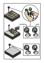
The condition of the underfloor heating must be inspected before and after casting by measuring the 

cable resistance as well as the insulation resistance between the wires and the sheathing, see page 3.       

• 

It must be possible to isolate the heating cable with an operating switch or with a branch circuit breaker 

which can also be on the control circuit. A label containing the type of the heating mat, the location and 

other information of the installation is to be fixed to the distribution board.

• 

A fault current switch with a nominal operating current of max. 30 mA has to be used in installations.

• 

The heating cables may not be switched on before the concrete screed has dried out. Follow the concrete 

screed manufacturer’s instructions.

• 

In premises where there is an explosion hazard, other consumer appliances may not be connected to 

the same branch circuit.

• 

The condition for the validity of Ensto Finland Oy’s warranty is a properly filled in installation protocol 

on the page 35.

• 

The warranty period for Ensto Tassu and Tassu S, is 10 years from the date of purchase but no longer than 

11 years from the date of manufacture. Warranty conditions, see 

www.ensto.com

.

TASSU

The Tassu heating cable is designed for installation 

in a medium with thermal conductivity of the same 

quality as that of concrete. 

The cable loading is approx. 20 W/m.

The minimum laying distance for the Tassu heating 

cable is 130 mm. 

The maximum power per square meter for the Tassu 

heating cable installation is 150 W/m2. 

INSTALLATION IN CONCRETE STRUCTURES 

1-STAGE CASTING (Fig. A1)

1. 

Compacted gravel

2. 

Thermal insulation

3. 

Construction paper

4. 

Reinforcement mesh

- Attach the heating cable directly to the rein-

forcement mesh.

5. 

Heating cable

- Installation depth is approx. 50 mm.

6. 

Floor sensor in protective tube

- Close the protective tube with tape or similar

7. 

Reinforced concrete floor slab

- The concrete must cover the entire cable

8. 

Damp proofing (if necessary)

9. 

Ceramic tile adhesive

10.  Soundproofing 

11.  Flooring material

- In direct heating hard, thermally conductive 

(e.g. ceramic tile).

- In storage heating, thermally insulating (e.g. 

parquet, cork or vinyl flooring).

12.  Thermostat

2-STAGE CASTING (Fig. A2)

1. 

Compacted gravel

2. 

Thermal insulation

3. 

Construction paper

4. 

First casting

5. 

Fixing strip

- Nail the fixing strip to the base casting. It is 

easiest to attach the strip before the concrete 

is fully set.

6. 

Heating cable

- The surface of the slab must be cleaned thor-

oughly before the cable is spread out.

Summary of Contents for TASSU

Page 1: ...POL RAK 08 19 12 2013 TASSU TASSU S Installationsanvisning Installation instruction Montavimo instrukcija Mont as instrukcija Paigaldusjuhend Instrukcja monta u LAV DEU HRV Montageanweisung Vodi za in...

Page 2: ...2 TASSU TASSU S PVC 5 0 x 7 5 mm t max 70 C 1 0 mm2 Al Cu XLPE R m Cu 0 5 mm2 6 0 m 10 0 m OK 30 mm r 40mm NOT OK...

Page 3: ...3 Rj Re Rj Re Tassu Tassu S Sensor L N PE PE L N L N PE PE L N...

Page 4: ...4 8 7 5 3 2 1 9 10 11 12 4 6 9 6 4 3 2 1 10 11 12 13 5 8 7 A1 Pmax 150 W m2 TASSU 20 W m A2 Pmax 150 W m2...

Page 5: ...5 6 5 3 2 8 7 1 4 11 7 5 6 4 3 2 1 8 10 9 9 8 7 6 5 4 3 2 1 D Pmax 80 W m2 C Pmax 100 W m2 B Pmax 110 W m2 TASSU S 10 W m...

Page 6: ...Kaapeleiden jatkos ja loppup t on oltava l mp kaapelin kanssa saman arvoisessa materiaalissa niit ei saa taivuttaa ja ne on kiinnitett v luotettavasti alustaansa Termostaatin anturin suojaputken kaar...

Page 7: ...eli on suunniteltu asennetta vaksi saneerauksen yhteydess vanhan lattiapinnan p lle kipsilevylattiaan tai puurakenteiseen lattiaan Kaapelin metrikuormitus on noin 10 W m Pienin asennusv li l mmityskaa...

Page 8: ...igt och ndringarna b r ritas in i slutritningen Golvv rmekablarna r konstruerade f r golvv rmeinstallationer och de f r endast installeras i eldfast p sten baserat material s att de inte uts tts f r m...

Page 9: ...ackumulerande uppv rmning isolerande material t ex parkett kork eller plastmatta 12 Termostat TV STEG GJUTNING Bild A2 1 Packat grus 2 V rmeisolering 3 Byggpapp 4 F rsta betonggjutning 5 Installation...

Page 10: ...Vid urholkningen b r konstruktionens b rf rm ga ocks beaktas Placera en metallplatta som brandskydd p st llen d r kabeln verstiger reglarna 7 Golvmaterial Golvmaterialet skall l mpa sig f r golvv rme...

Page 11: ...A fault current switch with a nominal operating current of max 30 mA has to be used in installations The heating cables may not be switched on before the concrete screed has dried out Follow the conc...

Page 12: ...able 7 Filler if necessary 8 Flooring material 9 Thermostat INSTALLATION IN PLASTERBOARD FLOORS Fig C 1 Plasterboard layer To be made according to national building regulations and manufacturer s inst...

Page 13: ...kt werden Gefahr einer berhitzung des Kabels DasHeizkabeldarfnichtdurchdieW rmeisolierunggef hrt sondernmussinMaterialverlegtwerden das eine gleichwertigeW rmeleitf higkeit aufweist Das Heizkabel darf...

Page 14: ...gesamte Kabel abdecken Die St rke der zweiten Schicht h ngt von den gew nschtenSpeichereigenschaftensowievom Bodenbelag ab 9 Feuchtigkeitsschutz falls erforderlich 10 Bodenflie en Klebstoff 11 Ger us...

Page 15: ...o das Kabel die Schiene kreuzt 7 Bodenbelag DasBodenmaterialmussf rFu bodenheizung geeignet sein Informationen diesbez glich k nnen beim Hersteller des Bodenmaterials eingeholt werden 8 Thermostat Fal...

Page 16: ...u ja Tassu S k ttekaablite garantiiaeg on 10 aastat alates ostukuup evast aga mitte rohkem kui 11 aastat valmistamiskuup evast Garantiitingimused vt www ensto com Klienditeenindus 372 6512104 Tehnilin...

Page 17: ...skiht vajadusel 7 Tugevdatud ehitusega kipsplaat Kui all oleva p randa ehitus on piisavalt tugev v ib keraamilised plaadid paigaldada ilma viimase kipsplaadikihita linoleumi alla on soovitatav paigald...

Page 18: ...liacijos Kabelio vijos kirstis negali Kabelis turi b ti sumontuotas med iagoje turin ioje vienod laidum Kabelio alt j gal galima pravesti per izoliacij ildomojo kabelio negalima pravesti per judamas s...

Page 19: ...giasieniame vamzdelyje u sandarintu galu 8 Antrasis atitinkamos mark s cementinio skie dinio sluoksnis su plastifikatoriais Skiedinys turi dengti vis kabel skaitant jungiam j mov bei gal n 9 Hidroizol...

Page 20: ...tatybinis tinkas Kabelio ir termostato daviklio tvirtinimui tarp grind tvirtinimo sij rekomenduojamas staty binis tinklas 4 ildymo kabelis 5 Grind temperat ros sensorius apsauginiame gofruotame arba l...

Page 21: ...j izmanto ssl guma str vas sl dzis ar nomin lo darba str vu l dz 30 mA Apsildes kabe us nedr kst iesl gt pirms betona virssl nis nav iz uvis Iev rojiet betona virssl a ra ot ja nor d jumus Telp s kur...

Page 22: ...kabelis piln b 7 Pildviela ja nepiecie ams 8 Gr das seguma materi ls 9 Termostats UZST D ANA UZ RE IP A PL T U GR DAS att C 1 Re ip a sl nis J izgatavo atbilsto i valsts b vnormat viem un ra ot ja no...

Page 23: ...yjne oraz miejsca zagro one p kaniem wylewki lub przegrzaniem przewod w piec sauny itp Pod czenie do przewodu zimnego oraz z cze ko cowe musz znajdowa si w tym samym materiale coprzew dgrzejny Niepowi...

Page 24: ...rzewcze typu Tassu S przeznaczone s do instalowania na starej pod odze na p ycie gipsowo kartonowej lub na pod odze drewnianej Moc przewodu wynosi ok 10W m Minimalna odleg o mi dzy przewodami Tassu S...

Page 25: ...a grija a i nacrte treba izraditi kvalificirani elektri ar ili in injer i to prema uputstvima proizvo a a a u skladu sa svim industrijskim pravilima i propisima Radni nacrt postavljanja mora sadr avat...

Page 26: ...0 W m Minimalni razmak za postavljanje Tassu kabela je 130 mm Maksimalna snaga je 150 W m2 POSTAVLJANJE U BETONSKE KONSTRUKCIJE JEDNOSLOJNO BETONIRANJE SLIKA A1 1 Kompaktirani ljunak 2 Toplinska izola...

Page 27: ...stavlja u utore koji se ispunjavaju gipsom na bazi kamena 6 Filer 7 Gips plo a Ukoliko je pod ispod dovoljno vrst plo ice se mogu postaviti i bez ovog sloja gips plo e ispod vinilnih podova se ipak pr...

Page 28: ...28 5 C 0 40 30 0 5 3 30 A Ensto Finland Oy Ensto Tassu Tassu S 10 11 www ensto com TASSU Tassu 20 Tassu 130 Tassu 150 200...

Page 29: ...29 1 A1 1 2 3 4 5 50 6 7 8 9 10 11 12 2 A2 1 2 3 4 5 6 7 8 9 10 11 12 13 TASSU S Tassu S 10 Tassu S 90 Tassu S 110 2 B 1 2 3 20 30 4 25x25 5 6 30 50 20 30 7 8 9 C 1...

Page 30: ...30 2 3 4 5 6 7 8 9 10 11 Tassu Tassu S D 1 2 3 4 5 6 40x30 7 8 RUS...

Page 31: ...31 c Tassu Tassu S o o o o o o o o 50 o o Tassu S 30 30 Ensto Ensto Tassu Tassu S 10 11 Ensto www ensto com...

Page 32: ...32 TASSU Tassu 20 120 240 150 300 Tassu 150 1 1 2 30 50 3 4 5 50 6 7 30 50 50 80 8 9 10 11 12 2 1 2 30 50 3 4 5 6 30 7 8 9 10 11 12 13 TASSU S Tassu S 10 Tassu S 90 120 100 1...

Page 33: ...33 2 3 20 30 4 25 25 5 6 30 50 20 30 7 8 9 C 1 2 3 4 5 6 7 8 9 10 11 D 1 2 3 4 5 6 40 30 7 8 80 C...

Page 34: ...Moc Powierzchnia Odleg o instalacji Povr ina poda Tip Snaga Du ina Otpor Snaga Povr ina Instalacije udaljenost m2 P W m Rj P m2 W m2 2 mm TASSU 1 0 1 7 TASSU1 150 7 350 1 6 2 7 TASSU2 240 11 220 80 2...

Page 35: ...ollinud Technin prie i ra Uzraugs Nadz r Supervizor P iv ys ja allekirjoitus Datum och underskrift Date and signature Datum und Unterschrift Kuup ev ja allkiri Data ir para as Datums un paraksts Data...

Page 36: ...service 358 200 29 007 Fax 358 20 476 2790 ensto ensto com www ensto com Ensto Finland Oy Ensio Miettisen katu 2 c 2 P O BOX 77 77 06101 Porvoo 06101 Finland 358 204 7621 358 204 762753 Ensto Ensek A...

Reviews: