12
7.
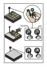
Floor sensor in protective tube
- Close the protective tube with tape or similar.
8.
Second casting
- The concrete must cover the entire cable
- The thickness of the second casting depends
on the desired storage charasterics and the
flooring material
9.
Damp proofing (if necessary)
10. Ceramic tile adhesive
11. Soundproofing
12. Flooring material
- In direct heating hard, thermally conductive
(e.g. ceramic tile).
- In storage heating, thermally insulating (e.g.
parquet, cork or vinyl flooring).
13. Thermostat
TASSU S
Tassu S heating cable is designed for renovation instal-
lation on top of old floors, on a plasterboard or in a
wooden structure floor.
The cable loading is approx. 10 W/m.
The minimum laying distance for the Tassu S heating
cable is 90 mm.
The maximum power per square meter for the Tassu
S heating cable installation is 110 W/m2.
INSTALLATION ON TOP OF AN OLD FLOOR (Fig. B)
1.
Old flooring
- Prepare the old flooring according to the floor-
ing manufacturer’s instructions.
- Level out the old flooring with plaster if nec-
essary.
2.
Adhesion layer (Primer)
- A renovation plaster is spread according to the
manufacturer´s instructions.
3.
Heating cable
- Installation depth is 20-30 mm
4.
Installation tape or mesh
- A cable can be attached to a concrete and slab
floor with installation tape
- Also a mesh (e.g. a thin wire mesh, approx.
25x25 mm) can be used. Attach the mesh and
cable with hot glue or similar.
5.
Floor sensor in protective tube
- Close the protective tube with tape or similar.
6.
Screed
- Thickness 30-50 mm when using gypsum, and
20-30 mm when using concrete. The screed must
cover the entire cable.
7.
Filler (if necessary)
8.
Flooring material
9.
Thermostat
INSTALLATION IN PLASTERBOARD FLOORS (Fig. C)
1.
Plasterboard layer
- To be made according to national building
regulations and manufacturer’s instructions. An
intact layer of plasterboard must be left under
the cables. Additional strips of plasterboard will
be attached to this.
2.
Heating cable
3.
Floor sensor in protective tube
- Close the protective tube with tape or similar.
4.
Plasterboard strips
- Attach the strips to the base.
5.
Grooves for heating cable
- The cable is laid in the grooves, which are filled
with a stone-based plaster.
6.
Filler
7.
Plasterboard
- If the floor structure underneath is sufficiently
rigid, the surface tiling can be performed with-
out a plasterboard layer; a layer of boards is
recommended under vinyl flooring.
8.
Damp proofing (if necessary)
9.
Ceramic tile adhesive (if necessary)
10. Flooring material.
11. Thermostat
INSTALLATION IN WOODEN STRUCTURES (Fig. D)
1.
Thermal insulation
2.
Aluminium foil
- Aluminium foil is spread over the insulation to
improve heat conduction.
3.
Attachment mesh
- A mesh is spread between the fixing battens
to attach the cable.
4.
Heating cable
5.
Floor sensor in protective tube
- Install the sensor at the floor joint and floor
material connection point without touching
the cable.
6.
Crossing the fixing battens
- The crossing points are notched to make them
loose, e.g. 40x30 mm; the durability of the
structure must also be taken into consideration.
- For flame proofing place a protective metal
plate where the cables crosses the runner.
7.
Flooring material
- Flooring material must be suitable for under-
floor heating, ask the manufacturer of the floor-
ing material.
8.
Thermostat
- A thermal cut-out must be used if necessary.
The maximum temperature of a flammable
material is 80°C.


