UNCONTROLLED COPY WHEN DOWNLOADED OR PRINTED
ENSTROM F-28F/280F SERIES MAINTENANCE MANUAL SUPPLEMENT 1
Rev.
8
13-3
Jan
15/19
SECTION 4
SYSTEM MAINTENANCE
NOTE
Removal or installation of equipment will change the aircraft empty
weight and empty weight c.g. These changes will be recorded on the
Basic Weight and Balance Record, as required.
4-1. GTX
345
NOTE
All work must be accomplished in accordance with the Enstrom F-
28/280F Series Maintenance Manual.
NOTE
Replacement of the GPS position source requires that the GTX 345 be
tested and shown to comply with 14 CFR Part 91.225 and 91.227.
4-1-1. Cleaning
A. The front bezel, keypad, and display can be cleaned with a microfiber cloth or with a soft
cotton cloth dampened with clean water. DO NOT use any chemical cleaning agents. Care
should be taken to avoid scratching the surface of the display.
4-1-2. GTX 345 Removal
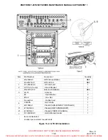
A. Remove power to the GTX 345 unit. Pull the
XPNDR
circuit breaker out. Disable the circuit
breaker by installing a cable tie or other similar device around the circuit breaker stem.
B. Insert the 3/32-inch hex drive tool into access hole on the unit face. Turn the hex tool
counterclockwise until the unit is forced out about 3/8 inch.
C. Pull the unit straight out of the rack.
4-1-3. GTX 345 Installation
CAUTION
Do not use excessive force when inserting the GTX 345 into the rack.
This may damage the connectors, unit, and/or unit rack. Be sure not
to over-tighten the unit into the rack. Torque exceeding 8 in-lb can
damage the locking mechanism.
A. Slide the GTX 345 straight into the rack until it stops, about one inch short of the final
position.
B. Insert the 3/32-inch hex drive tool into access hole at the bottom of the unit face.
C. Turn the hex tool clockwise while pressing on the left side of the bezel until the unit is
firmly seated in the rack.
Visit www.enstromhelicopter.com for instructions to order an original manual and to register for email notification of updates.


