UNCONTROLLED COPY WHEN DOWNLOADED OR PRINTED
ENSTROM F-28F/280F SERIES MAINTENANCE MANUAL SUPPLEMENT 1
Rev.
8
13-4
Jan
15/19
D. Count the number of complete revolutions the hex screw can be turned, not exceeding 8
in-lb of torque. Be careful not overtighten. Three turns is the minimum for proper
installation. If fewer than three turns are possible, ensure there are no obstructions to the
unit fully seating in the rack.
E. Remove the cable tie or other similar device from the
XPNDR
circuit breaker stem and
push the stem in to set the circuit breaker.
F. Continue to paragraph 4-1-6 for system checkout.
4-1-4. GAE Altitude Encoder Removal
A. Remove power to the GTX 345 unit. Pull the
XPNDR
circuit breaker out. Disable the circuit
breaker by installing a cable tie or other similar device around the circuit breaker stem.
B. Remove the transponder (para. 4-1-1).
C. Remove the static line attached to the altitude encoder.
D. Disconnect the wiring harness at the altitude encoder.
E. Remove the two screws securing the unit to the backplate.
4-1-5. GAE Altitude Encoder Installation
A. Secure the altitude encoder to the backplate assembly with two screws, torque to 8 in-lb.
B. Connect the wiring harness to the altitude encoder.
C. Secure the static line to the altitude encoder using standard practice.
D. Install the transponder (para. 4-1-3).
E. Remove the cable tie or other similar device from the
XPNDR
circuit breaker stem and
push the stem in to set the circuit breaker.
F. Perform static system and transponder checks in accordance with
GTX 345 Part 27 AML
Maintenance Manual
, Document No. 190-00734-21, Section 8.4.2.
4-1-6. System
Checkout
A. No software or configuration loading is required if the removed GTX is reinstalled.
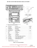
1) Verify configuration parameters in accordance with Figure 13-3.
B. If a new or repaired or exchange GTX is installed:
NOTE
A computer or laptop connection to the GTX via the USB-B
connection may be required for software updates, configuration set-
ups, and checkout. Access the USB-B connector via the console side
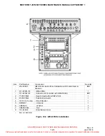
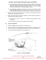
panel. Refer to Figure 13-1.
Visit www.enstromhelicopter.com for instructions to order an original manual and to register for email notification of updates.

