background image

Multi-Function Control ETMFC610 

http://www.entecene.co.kr 


225

EN

HANCED

 TEC

HNOLOGY


8.2.9. User Curve - Time Overcurrent Curves 

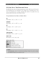
The ETMFC610 has a total of 62 kinds of standard curves: ANSI / IEEE curves, IEC curves, US 
curves and Definite time curves, KEPCO ES curves, KERI curves, 4 user-defined curves, 3 fuse 
curves, 32 nonstandard curves. According to Standard ANSI / IEEE C37.112 and IEC 255-3, trip 
operation times and reset times can be defined as follows. 
 

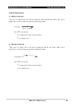
The operation times and reset times are defined as follows : 

 
US 

Trip Time(Sec)  = TD 

× 

(

α

 / (M

β

-

1) 

+


γ

) + TA 


ANSI/IEEE 

Trip Time(Sec)  = TD 

× 

(

α

 / (M

β

-

1) 

+


γ

) + TA 


IEC 

Trip Time(Sec)  = TD 

×

  (

α

 / (M

β

-

1)) + TA 


ES 

Trip Time(Sec)  = TD 

×

  (

α

 / (M

β

-

1) 

+


γ

)  + TA 


USER-DEFINED 

Trip Time(Sec)  = TD 

×

  (

α

 / (M

β

-

1) 

+


γ

) + TA 


RESET TIME 

Reset Time(Sec) = TD 

×

 (Rt / (1

-

M

2

)) 


Table 8-3. Curve Factor 

TD  

Time dial 

TA 

Time  adder 

α

β

γ


Characteristic constant 

Multiples of pickup current 

Rt 

Reset characteristic constant 


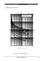
 NOTE : 

 “CB  clearing  time  curves”

  are  used  when rated  voltage  of CB is 15

  or 27

,  otherwise 

which added 30

(

±

4

) are used when it is 38


Summary of Contents for ETMFC610

Page 1: ...ELECTRONIC CO LTD ENTEC Copyright 2018 by ENTEC ELECTRIC ELECTRONIC CO LTD all right reserved Forerunner Distribution Automation Release Date Aug 2019 Manual Revision 1 04 MULTI FUNCTION CONTROL ETMFC610 USER S MANUAL ...

Page 2: ......

Page 3: ...D TECHNOLOGY Release Note May 2018 Ver1 00 New user manual for ETMFC610 Oct 2018 Ver1 01 Add Multi Bit Protocol Feb 2019 Ver1 02 Add FI Auto Reset function May 2019 Ver1 03 Add Negative Sequnce Over Voltage function Aug 2019 Ver1 04 Modify to the latest H W Drawings ...

Page 4: ...tion Controls 15 2 7 Cold Load Pickup 16 2 8 Loop Control 16 2 9 Monitoring 17 2 10 Recorder 25 2 11 Communications 31 3 APPLICATION 32 4 DIMENSIONS AND CONSTRUCTION 33 5 SIDE PANEL CONSTRUCTION 34 5 1 Communication Port 35 5 2 NTC Connector 37 5 3 Current Input Connector 38 5 4 Voltage Input Connector 38 5 5 Status Inputs Connector 39 5 6 Outputs Connector 39 5 7 SCADA Connector Option 40 5 8 Pow...

Page 5: ... 1 8 User LED Section 52 6 1 9 Set Group Status Section 53 6 2 LCD Display 54 6 2 1 Menu Structure Tree 54 6 2 2 GLOBAL Setting 57 6 2 3 GROUP Setting 58 6 2 4 Event 59 6 2 5 Maintenance 59 6 2 6 Time 59 6 2 7 Status 59 6 2 8 Metering 59 6 3 Using the LCD Menu 60 6 3 1 Initial Screen 60 6 3 2 Main Menu 63 6 3 3 Setting Example 63 6 3 4 Setting Save 64 7 GLOBAL SETTING 65 7 1 General Setting 65 7 1...

Page 6: ... 2 2 Ground Time Overcurrent 51G 200 8 2 3 Negative Sequence Overcurrent 51Q 46 204 8 2 4 Phase Instantaneous Overcurrent 50P 208 8 2 5 Ground Instantaneous Overcurrent 50G 210 8 2 6 Sensitive Earth Fault 50SG 212 8 2 7 Negative Sequence Instantaneous Overcurrent 50Q 214 8 2 8 Inrush Restraint 216 8 2 9 User Curve Time Overcurrent Curves 225 8 3 Directional Controls 67 260 8 3 1 Phase Directional ...

Page 7: ...Cycle Summary 311 9 4 System Event 312 9 5 Set Change Event 313 9 6 Load Energy Event 314 9 6 1 Load Energy Min Event 314 9 6 2 Load Energy Hour Event 316 9 6 3 Load Energy Day 317 9 6 4 Load Energy Field Configuration 318 9 7 Diagnostic Event 319 9 8 PQM Event 321 9 9 Load Current Alarm Event 322 9 10 Clear Saved Data 324 10 MAINTENANCE 325 10 1 Count 325 10 1 1 ETMFC610 Count 325 10 1 2 Fault Co...

Page 8: ... 1 Current 343 13 2 Voltage 344 13 3 Frequency 346 13 4 Power 347 13 5 Energy 348 13 6 Demand Current and Power 349 13 7 Unbalance 351 13 8 Harmonics 352 13 9 True R M S 352 13 10 Controller Reference 353 14 MAINTANANCE 354 14 1 Warning Events 354 15 PLC function 357 16 Function of File Transfer Protocol 358 16 1 Patching firmware to upgrade 358 16 2 COMTRADE 359 16 2 1 File format and Name 359 16...

Page 9: ...Multi Function Control ETMFC610 http www entecene co kr vii ENHANCED TECHNOLOGY 17 3 Security 362 17 3 1 SSL TLS 362 17 3 2 AES 362 ...

Page 10: ......

Page 11: ...programmable lamps etc to provide convenient application in various distribution environment Especially PLC Programmable Logic Control Scada I O ports and user programmable lamps does not require any H W change for implementing number of Input Output signal and status indications Moreover it is operated based on Linux OS that can provide the user with comfortable and useful operation technology su...

Page 12: ...ence Directional Controls Auto Sectionalizer Loop Control Tie Point Switch Loop Control PROTECTION Dual Phase Time Overcurrent Elements Dual Phase Instantaneous Overcurrent Elements Dual Ground Time Overcurrent Elements Dual Ground Instantaneous Overcurrent Elements Dual Sensitive Earth Fault Elements Dual Negative Sequence Time Overcurrent Elements Dual Negative Sequence Instantaneous Overcurrent...

Page 13: ... Power Elements Two Directional Power Elements Phase Current Ground Current Negative Sequence Current Active Power and Reactive Power Demand Elements Phase Difference Synchro Check Open Phase Live Line Block Fault Locator Load Current Alarm Power Factor Lead and Lag Live Line Operation Count Contact Wear per Phase Battery Automatic Load Test Battery Management Power Quality Interrupt Sag and Swell...

Page 14: ...ays Peak Load Energy in every hour last 8 640 events Peak Load Energy in every day last 8 640 events Diagnostic Event Recorder last 2 000 events PQM Detection Event Recorder last 1 500 events Load Current Alarm Event Recorder last 1 500 events NOTE 1 The maximum number of all events except fault waveform to be stored can be increased according to user requests 2 According to sting waveform can sup...

Page 15: ...Ia Ib Ic In Iq Single Phase and Three Phase Active Power kW and Reactive Power kVar Source Load side Voltage and Current Unbalance Voltage and Current Harmonics THD 2nd 31th order Voltage and Current True R M S ETMFC610 Condition Reference Battery Voltage Charger Voltage and Charger Current Battery Capacity ETMFC610 Internal Temperature ETMFC610 External Temperature System Power 12V 12V Reference ...

Page 16: ...ds 20 8 Character LCD Display 49 LED indicators Fault indications Sequence status Battery status etc Setting Range Help Messages Access Security 3 Passwords with Different Authorities OTHERS Programmable Logic Control PLC Time Synchronism Device IRIG Option Wifi Option AUXILIARY INPUTS 12 Opto isolated Programmable Inputs Option AUXILIARY OUTPUTS 8 Opto isolated Programmable Outputs Option ...

Page 17: ...24Vac 20 Nominal Battery Voltage 24Vdc Power Consumption 8 4W at 24V dc USER AVAILABLE DC POWER OUTPUT DC Power Voltage 24Vdc or 12Vdc 15Vdc option DC Power Continuous 40W 60W 1 min VOLTAGE TRANSFORMER INPUTS VT Voltage Inputs Va Vb Vc Vr Vs Vt Input Voltage Range Phase Neutral Continuous 8V Burden 0 002VA 4V VOLTAGE TRANSFORMER INPUTS VT Option Voltage Inputs Va Vb Vc Vr Vs Vt Input Voltage Range...

Page 18: ...ous 0 6A 1 second Burden 0 0375VA 0 05A CONTROL INPUTS Option Control Inputs 12 Channel Nominal Voltages and Operating Range 12V 24Vdc 15 20 125Vdc 15 20 250Vdc 15 20 Operating current 5mA at Nominal Voltages CONTROL OUTPUT CONTACTS Option Control Outputs 8 Channel 300Vac 350Vdc Varistor for differential surge protection Operate Release time 5ms at 20 68 Maximum operating power Table 2 1 Control O...

Page 19: ...Comm ports Conducted disturbance immunity IEC 61000 4 6 2013 10 V at 150 kHz 80 MHz Power frequency magnetic field immunity IEC 61000 4 8 2009 100 A m Continuous 1 000 A m 3s Voltage dips interruption and variation immunity IEC 61000 4 11 2004 Voltage disp immunity test 0 40 70 80 Voltage interruptions immunity test 0 Voltage variations immunity test 70 30 cycles Test for immunity to conducted com...

Page 20: ...el 40 4day Relative Humidity 93 Damp heat Cyclic IEC 60068 2 30 2005 Severity Level 25 to 55 2cycles Relative Humidity 95 Vibration IEC 60255 21 1 1988 Shock and bump IEC 60255 21 2 1988 Seismic IEC 60255 21 3 1993 Safety Dielectric Strength IEC 60255 27 2013 2000 Vac on Control inputs control outputs and analog inputs communication for 1minute Impulse IEC 60255 27 2013 0 5 J 5 kV 1 2 50 Insulatio...

Page 21: ...CURRENT METERING Rated current AC 0 6 Arms IA IB IC IN 0 5 mA 0 5 of reading 0 03 1 5 A 0 5 ISEF 0 005 mA 0 5 of reading 0 5 16 0 mA 1 I1 I2 3I0 0 01 A 3 of reading 0 003 1 5A 1 POWER METERING Apparent Power 1 2 Rated Voltage 80 Rated Current 0 03 Active Power 0 7 PF 1 1 PF 0 87 Rated Voltage 80 Rated Current 0 03 Reactive Power 0 7 PF 0 1 PF 0 5 Rated Voltage 80 Rated Current 0 03 FREQUENCY METER...

Page 22: ...H W option Permanent Temporary FI Time 1 to 180 sec in steps of 1 sec Type I Delay Time 0 01 to 180 00 sec in steps of 0 01 sec Dropout Level 96 to 98 of Pickup Pickup Level Accuracy 5 of setting time or 20 Inrush Duration Time Phase Ground S E F NEQ Inrush Duration Time 0 00 to 600 00sec in steps of 0 01 sec Make Use I NO YES Timing Accuracy 5 of setting time or 20 Fault Indication Auto Reset Aut...

Page 23: ...N2 N3 N4 User programmable curves USER 1 USER 2 USER 3 USER 4 McGraw Edison Non Standard Curves 32 Fuse Non standard Curve 3 RI HR FR Time Dial 0 01 to 15 00 in steps of 0 01 Time Adder 0 00 to 600 00s in steps of 0 01s Minimum Response Time 0 00 to 10 00s in steps of 0 01s Reset Type INSTANTANEOUS LINEAR Low Set Definite Time OFF 0 01 to 600 00s in steps of 0 01s Pickup Level Accuracy 5 Timing Ac...

Page 24: ...NEQ Function DISABLE ENABLE Restore Minimum Time 0 01 to 600 00s in steps of 0 01s Inrush Restraint Reset Phase Ground Neg Seq Rest Current 10 1600A in steps of 1A SEF Rest Current 0 1 160 0A in steps of 0 1A Reset Time 0 01 to 600 00s in steps of 0 01s Phase Ground Neg Seq Curves Curve Type Total 62 Curves ANSI IEEE Normally Very Extremely IEC Normally Very Extremely Long Time Inverse Short Time ...

Page 25: ...n Delay 1 5cycle Ground Sensitive Earth Fault Directional Control Polarizing Voltage Zero Sequence Voltage 3V0 For voltage element polarizing the source VTs must be connected in Wye Detecting Direction NONE FORWARD REVERSE Maximum Torque Angle 0 to 359 Lag in steps of 1 Lag Minimum Polarizing Voltage OFF 0 10 to 0 80 xVT in steps of 0 01xVT Block OC NO YES Angle Accuracy 2 Internal Operation Delay...

Page 26: ...zer Operation Time Delay 0 00 to 600 00sec in steps of 0 01sec Auto Sectionalizer Reset Time Delay 1 00 to 600 00sec in steps of 0 01sec Voltage Response Side to Tie Point Switch VS VL VS VL Tie Point Switch Operation Count 1 5 Shot in steps of 1 Shot Tie Point Switch Close Operation Time Delay 0 00 to 600 00sec in steps of 0 01sec Tie Point Switch Open Operation Time Delay 0 00 to 600 00sec in st...

Page 27: ...rmal Voltage 0 10 to 1 40xVT in steps of 0 01xVT Active Voltage Type Any One 1P Any Two 2P All Three 3P Over Voltage 1 2 Function DISABLE ENABLE Pickup Level 0 10 to 1 40xVT in steps of 0 01xVT Time Delay 0 00 to 600 00s in steps of 0 01s Active Voltage Type Any One 1P Any Two 2P All Three 3P Neutral Over Voltage 1 2 Function DISABLE ENABLE Pickup Level 0 10 to 1 40xVT in steps of 0 01xVT Time Del...

Page 28: ...ormal Voltage 0 00 to 1 40xVT in steps of 0 01xVT Minimum Normal Current OFF 1 to 630A in steps of 1A Frequency Decay Function DISABLE ENABLE Pickup Level Hz sec 0 01 to 5 00 in steps of 0 01 sec Time Delay 0 00 to 600 00s in steps of 0 01s Reset Time 0 00 to 600 00s in steps of 0 01s Minimum Normal Frequency 45 00 to 65 00 in steps of 0 01 Minimum Normal Voltage 0 00 to 1 40xVT in steps of 0 01xV...

Page 29: ...9 in steps 0 01 Time Delay 0 00 to 600 00sec in steps of 0 01sec Polarizing Power 3 Phase Active Power and Reactive Power Level Accuracy 5 Timing Accuracy Max 50 at 0 trip time delay 5 of trip time or 20 Demand Function DISABLE ENABLE Pickup Level Phase Ground Neg Seq Current 10A to 1600A in steps of 1A Active Power 0 01 to 300 00 MW in step of 0 01 MW Reactive Power 0 01 to 300 00 Mvar in step of...

Page 30: ... 05 Timing Accuracy 5 of setting time or 20msec Syncro Check Function DISABLE ENABLE Dead Voltage Maximum Level 0 10 to 1 40xVT in steps of 0 01xVT Live Voltage Minimum Level 0 10 to 1 40xVT in steps of 0 01xVT Maximum Voltage Difference 0 10 to 1 40xVT in steps of 0 01xVT Maximum Angle Difference OFF 20 0 to 80 0 in steps of 0 1 Maximum Frequency Difference Slip Freq 0 5 to 5 00Hz in steps of 0 0...

Page 31: ... steps of 0 01s Level Accuracy 5 Timing Accuracy 5 of setting time or 20msec Fault Locator Function DISABLE ENABLE Total Length of Feeder 0 1 to 99 9 of 0 1km Real impedance of the feeder positive seq 0 01 to 99 99 of 0 01ohms Imaginary impedance of the feeder positive seq 0 01 to 99 99 of 0 01ohms Real impedance of the feeder zero seq 0 01 to 99 99 of 0 01ohms Imaginary impedance of the feeder ze...

Page 32: ...ickup Timing Accuracy 5 of setting time or 20msec Operation Counter Function DISABLE ENABLE Alarm Count 1 to 20000 in steps of 1 Reset Count 0 to 10000 in steps of 1 Contact Wear Function DISABLE ENABLE Alarm Pickup Level 0 0 to 50 0 in steps of 0 1 Time Delay 0 00 to 1 00s in steps 0 01s Interruption Current at Point 1 Max Operation 1 00 to 600 00kA in steps of 0 01kA Number of Operation at Point...

Page 33: ...eps of 0 01xVT Time Delay 0 5 to 10 0cycle in steps of 0 5 cycle Swell Pickup Level OFF 1 01 to 1 50xVT in steps of 0 01xVT Time Delay 0 5 to 10 0cycle in steps of 0 5 cycle Harmonics Voltage Total Harmonics Pickup Level OFF 0 5 to 100 0 in steps of 0 1 Voltage Total Harmonics Time Delay 0 00 to 600 00sec in steps of 0 01sec Current Total Harmonics Pickup Level OFF 0 5 to 100 0 in steps of 0 1 Cur...

Page 34: ...e Delay 0 00 to 600 00sec in steps of 0 01sec Current Unbalance THD Detect Limit Current 0 to 630A in steps of 1A Level Accuracy at VT 0 02 at CVD 0 05 or 5 Timing Accuracy 5 of setting time or 20msec System Power Function OFF ON 12V Pickup OFF 0 1 to 10 0 V in steps of 0 1V Time Delay 0 01 to 10 00 sec in steps of 0 01 sec 12V Pickup OFF 0 1 to 10 0 V in steps of 0 1V Time Delay 0 01 to 10 00 sec...

Page 35: ...type Data Channels Analog 14 Channels Ia Ib Ic Ig Isef I1 I2 3I0 Va Vb Vc Vr Vs Vt Storage capacity 1 500 events FAULT WAVEFORM CAPTURE Trigger Source Fault Pickup Fault Timeout Elements Data Channels Current 5 Channels Ia Ib Ic Ig Isef Voltage 6 Channels Va Vb Vc Vr Vs Vt Digital Input Port Status 8 or 20 Channels IN101 112 IN201 208 Digial Output Relay 8 or 16 Channels OUT101 108 OUT201 207 OUT2...

Page 36: ...e Group Setting Change Group 1 2 3 4 5 6 Storage Capacity Total 2 000 Events LOAD ENERGY 1 Average Load Minute Trigger Source Demand Current A B C N Demand Voltage A B C R S T Demand Real Power A B C 3ф Positive A Positive B Positive C Positive 3ф Negative A Negative B Negative C Negative 3ф Demand Reactive Power A B C 3ф Positive A Positive B Positive C Positive 3ф Negative A Negative B Negative ...

Page 37: ...thour 3ф Positive Varhour 3ф Negative Watthour 3ф Negative Varhour 3ф Trigger Time every 1 hour Storage Capacity Total 8 640 events 360 days 3 Peak Load Day Trigger Source Demand Current A B C N Demand Voltage A B C R S T Demand Real Power A B C 3ф Positive A Positive B Positive C Positive 3ф Negative A Negative B Negative C Negative 3ф Demand Reactive Power A B C 3ф Positive A Positive B Positive...

Page 38: ...emory Fail Flash Rom Fail Circuit Voltage Fail Event Fail Count Fail DO Fail Close Fail Open Fail etc Trigger Time every 5 msec Trigger type Pick up and Dropout Storage Capacity Last 2 000 Events PQM EVENT RECORDER Trigger Source Interrupt Detect Voltage Sag Detect Voltage Swell Detect Voltage Current Harmonics Detect Voltage Current Unbalance Detect Under Over Voltage Detect Under Over Frequency ...

Page 39: ...00 or 0 to 65 534 Diagnostic Counter 0 to 1 000 000 or 0 to 65 534 Operation Counter 0 to 1 000 000 or 0 to 65 534 Fault Counters 0 to 1 000 000 or 0 to 65 534 PQM Counters 0 to 1 000 000 or 0 to 65 534 Communication Counter 0 to 1 000 000 or 0 to 65 534 User Counter 0 to 1 000 000 or 0 to 65 534 NOTE Depending on the 16bit Count Use setting in the menu GLOBAL SETTING GENERAL DEVICE OTHERS the rol...

Page 40: ...ceeds 65 534 CONTACT WEAR Phase A Wear 0 0 to 100 0 Phase B Wear 0 0 to 100 0 Phase C Wear 0 0 to 100 0 PEAK CURRENT Phase A B C Peak Current Ground Peak Current and Negative Sequence Peak Current Trigger Source Load Current Alarm Detect ENERGY Positive Active Power Energy A B C 3ф 0 to 60 000 kWh or 0 to 999 999 999 kWh Positive Reactive Power Energy A B C 3ф 0 to 60 000 kVarh or 0 to 999 999 999...

Page 41: ... Modbus IEC60870 5 101 and Multi Bit Protocol Interface Software Side panel RS232 2 RS232 1200 115200bps None Odd or Even Parity 7 or 8 Data bits 1 or 2 Stop bit DNP 3 0 Modbus IEC60870 5 101 and Multi Bit Protocol Interface Software Side panel RS485 RS485 1200 115200bps None Odd or Even Parity 7 or 8 Data bits 1 or 2 Stop bit DNP 3 0 Modbus IEC60870 5 101 and Multi Bit Protocol Side panel EN1 EN2...

Page 42: ...and when the switch body or sectionalizer body Sectionalizer type must be selected If the selected control type and the body type do not match erroneous operation or non operating occurs But the protection function fault trip is active on Protection type and when the CB or fault interrupters body Protection type must be selected If the selected control type and the body type do not match erroneous...

Page 43: ...47 110 304 128 25 4 6 5 330 10 LOOP CONTROL CLOSE BLOCK OPEN BLOCK GAS LOW 950 RS232 DBG RX TX RS232 1 CT 8 7 6 5 4 3 2 F01 8 7 6 5 4 3 2 E01 IA IB IC IN VA VB VC VR VS VT K01 2 3 4 5 6 7 8 9 10 PT POWER IN PW2 OUT PW1 OUT Rect OUTPUT INPUT PW BAT BAT AC24 AC24 G01 2 3 4 P N P N H01 2 3 4 24V 0V P01 2 3 I01 2 3 4 5 6 7 8 FUSE FUSE RS232 2 RS485 M10 9 NTC OUT201 202 OUT203 204 OUT205 OUT206 OUT207 ...

Page 44: ... AKZ 950 7P AKZ 950 7P Digital Input OUTPUT 10x Option AKZ 950 8P AKZ 950 5P Digital Output POWER1 OUT AKZ 950 3P DC21 30V Motor power POWER2 OUT AKZ 950 4P Modem power POWER IN AKZ 960 4P AC24V Battery RS232 DBG RX TX RS232 1 CT 8 7 6 5 4 3 2 F01 8 7 6 5 4 3 2 E01 IA IB IC IN VA VB VC VR VS VT K01 2 3 4 5 6 7 8 9 10 PT POWER IN PW2 OUT PW1 OUT Rect OUTPUT INPUT PW BAT BAT AC24 AC24 G01 2 3 4 P N ...

Page 45: ...Pin Description Pin Signal Description Figure 5 2 RS232 1 DCD Data Carrier Detect 2 RXD Receive Data IN 3 TXD Transmit Data OUT 4 DTR Data Terminal Ready OUT 5 GND Ground 6 DSR Data Set Ready IN 7 RTS Request To Send OUT 8 CTS Clear To Send IN 9 N C No Connection 2 RS485 PORT RS485 has 3pins as in Table 5 3 RS485 Pin Description Table 5 3 RS485 Pin Description Pin Description Figure 5 3 RS485 1 RS...

Page 46: ...n Wire Color 10Base T Signal 100Base TX Signal 1 White Green Transmit 2 Green Transmit 3 White Orange Receive 4 Blue Unused 5 White Blue Unused 6 Orange Receive 7 White Brown Unused 8 Brown Unused 4 IRIG B Connector Option It is a IRIG B connector for time synchronization function using Time Synchronization module Input current 4 mA at 5 V typical Table 5 5 IRIG B Pin Description Figure 5 5 IRIG B...

Page 47: ...ils on Wifi connections Table 5 6 WIFI Pin Description Figure 5 6 WIFI Connector Pin Description SMA Connector 1 Connecting the SMA antenna cables 5 2 NTC Connector A terminal that connects the battery temperature compensation sensor NTC 10 B25 85K 3435 Table 5 7 NTC Pin Description Figure 5 7 NTC Thermistor Connector Pin Description NTC Connector 01 NTC Thermistor NTC 10 B25 85K 3435 02 WIFI M10 ...

Page 48: ...5 8 Current Input Terminal Table 5 8 Current Input Pin Description Pin IA IB IC IN SEF Description A phase B phase C phase N phase SEF 5 4 Voltage Input Connector Voltage connector receives source side 3 phases A B C voltages and load side 3 phases R S T voltages Pin arrangement is as follow table Connector type is STLZ950 8P Table 5 9 Voltage Input Pin Description Pin VA VB VC VR VS VT Default LC...

Page 49: ...put where sending a control signal its pin arrangement is as follow Table 5 11 Output Pin Description Figure 5 11 Output Terminal Connector Pin Description Output Connector 1 2 OUT201 OUT202 OPEN 3 4 OUT203 OUT204 CLOSE 5 6 OUT205 OPEN 7 8 OUT206 CLOSE 9 10 OUT207 Reserve 11 12 OUT214 Reserve Open operation is controlled by two ports of OUT201 and OUT202 and operates when OUT201 is high and OUT202...

Page 50: ...ts from the control element 5 8 Power Input Battery Input Connector Power Input Connector for ETMFC610 s AC24V Power Supply It is a battery input connector to charge the battery using inner charger circuit Table 5 12 Power Battery Input Pin Description Figure 5 13 Power Battery Input Thermistor Connector Pin Description Power Battery Input Connector 1 2 BATT INPUT 3 4 AC 24V INPUT 5 4 3 2 D01 8 7 ...

Page 51: ...brupt recharge and voltage steady circuit to prevent over recharge Charge power supply is 24Vac equal with Relay Module Charging device charges up to 80 percent of battery with constant current from 80 to 100 percent of battery with constant voltage to make sure that there is not any danger of overcharging To measure temperature in charging circuit it helps to compensate with charging voltage 26 4...

Page 52: ...ry goes down below 19 voltage On Power Down status if the external power is re supplied or the Power Switch is changed from OFF to ON Control Module becomes operating as normal When AC Power is not supplied in order to operate it by Power Switch turn it OFF for 5 seconds and then turn it ON When it turns ON without Battery its power will be down after 10 minutes Figure 5 15 Power line and Power Pr...

Page 53: ...Multi Function Control ETMFC610 http www entecene co kr 43 ENHANCED TECHNOLOGY 5 12 Typical Wiring Diagram Figure 5 16 Typical Wiring Diagram 2 1 ...

Page 54: ... selected functions and to indicate selected function and operation status as below Directly control the switch or CB Verify control status View system status View metering value View information stored in ETMFC610 unit View and change ETMFC610 settings Figure 6 1 User Interface Panel MULTI FUNCTION CONTROL ETMFC610 MECHNISM LOCK 닫힘 열림 1 3 5 2 4 6 AC SUPPLY CHARGER BATTERY VA VR VB VS VC VT A B C ...

Page 55: ...ds a trip signal to the Switch or CB CLOSE Pressing CLOSE push button sends a close signal to the Switch or CB ETMFC610 has a feature of Manual Close Time Delay The Close Time Delay allows a delay of 0 00 to 600 00 seconds after pressing the close push button before closing the tank During the manual close delay time if the CLOSE push button is pressed it closes immediately without waiting for the...

Page 56: ... PROTECTION ENABLED is ON all fault indication and protection elements and are operating however Ground fault and Sensitive Earth Fault Elements are individually set for enable or disable on front panel by LED ON OFF button GROUND ENABLED GROUND ENABLED LED is ON and OFF by pressing the GROUND ENABLED push button When the PROTECTION ENABLED and GROUND ENABLED LEDs are both ON ground fault indicati...

Page 57: ... operates only in Fault Indication type CONTROL LOCKED When the CONTROL LOCKED LED is on all the functions in the operation section and Local control section are locked These can be unlocked by pressing the CONTROL LOCKED push button at the front panel NOTE Even though Control Locked function is locked OPEN Battery Load Test Trip Test Lamp Test and menu control section can be normally operated REM...

Page 58: ...ht up If ESC button is pressed or if ENT button is not pressed for a long time the setting group before the GROUP SELECT push button control will be returned BATT TEST When BATT TEST push button is pressed battery load test is run On Test Battery is disconnected from the charge circuit and connected the battery with load resistor and check the battery Load resistor shall be connected with AC suppl...

Page 59: ...the menu window and the changing of the setting value METER Up arrow key is used to move to the meter menu operable in menu starting mode AWAKE Down arrow key is used for panel awake from sleep mode EVENT Left arrow key is used to move to the event menu operable in menu starting mode SET Right arrow key is used to move to the setting menu operable in menu starting mode FUN To move to main menu whe...

Page 60: ...y The ESC key can be used to cancel data input mode and return to the previous menu ENT Key ENT key is used to select a menu by using Up and Down arrow key Enter key is also used to accept a new setting by using Up or down arrow key Key Use the left and right arrow keys to move cursor when you are in the data input mode and when you change display message Key Use Up and Down arrow keys to move thr...

Page 61: ...d off by FI RESET command 6 1 5 Voltage Element Section Indicates that voltage element is occurred PHASE DIFFERENCE Shows a Phase Difference state between source side and load side voltage ABC RST LIVE Show Live Line status of source side and load side VA VR VB VR and VC VT Shows Open Phase Status on each phase Figure 6 8 Voltage Elements Section 6 1 6 System Diagnostic Section Indicates Diagnosti...

Page 62: ...cally 6 1 8 User LED Section Status of PLC logic which is set by a user is displayed PLC logic is set in ETMFC610 ETIMS Interface Software Factory default setting is as follows Figure 6 11 User LED Section Table 6 1 Default User LED Function User LED PLC Logic Name Description ULED1 MACHANISM LOCK The LED is ON when status of ETMFC610 is mechanism lock ULED2 CLOSE BLOCK The LED is ON when status o...

Page 63: ...GY 6 1 9 Set Group Status Section GROUP It displays the currently applied Set Group to ETMFC610 Please refer to the explanation of GROUP SELECT button in 6 1 2 Local Control Section for procedure of changing the set group locally Figure 6 12 Set Group Status Section 1 3 5 2 4 6 ...

Page 64: ... is used for a user to operate conveniently and to check operation status clearly Figure 6 13 Initial Logo and Main Menu 6 2 1 Menu Structure Tree Screen structure consists Initial Logo and Main menu Initial screen and all menus are round robin algorithm Menu screen is divided in to Setting and Event management menu Main menu has 7 sub menus ...

Page 65: ...ulti Function Control ETMFC610 http www entecene co kr 55 ENHANCED TECHNOLOGY NOTE Menu Structure Tree may be different according to the version and option of ETMFC610 Figure 6 14 Menu Structure Tree 1 2 ...

Page 66: ...lti Function Control ETMFC610 http www entecene co kr 56 ENHANCED TECHNOLOGY ⓐ NOTE Menu Structure Tree may be different according to the version and option of ETMFC610 Figure 6 14 Menu Structure Tree 2 2 ...

Page 67: ...s menu is only applied when Fault Indication type is set in MAIN MENU GLOBAL SETTING GENERAL DEVICE CONTROL TYPE menu PASSCODE Set items related to passcode security Consists of PASSCODE1 PASSCODE2 and PASSCODE 3 PASSCODE 1 is applied when changing General Global settings and Group Settings and PASSCODE 2 is applied when communication setting is changed PASSCODE 3 is applied when clearing or reset...

Page 68: ...TTINGS settings are applied to ETMFC610 1 3 5 2 4 6 Figure 6 15 GROUP SELCT Button and GROUP Setting The GROUP SELECT button is used to select a set group applied to present ETMFC610 Please refer to the explanation of GROUP SELECT button in 6 1 2 Local Control Section for procedure of changing the set group locally All set groups have the same submenus Each set group is classified into FAULT INDIC...

Page 69: ...d is displayed CONTACT WEAR Shows damaged status contact life of switch DATA RESET Maintenance related data is Reset CONTROLLER INFO Present ETMFC610 information is displayed MECHNISM SCALE Correction scale factor for main body sensor is displayed For more detail information please refer to 10 MAINTENANCE 6 2 6 Time Present time can be set and checked If GLOBAL SETTING GENERAL DEVICE TIME ZONE Tim...

Page 70: ...c information of ETMFC610 NORMAL It displays normal status of ETMFC610 ALARM It displays self diagnostic alarm of ETMFC610 ERROR It displays self diagnostic error of ETMFC610 In this status ETMFC610 is in significantly abnormal status so ETMFC610 blocks to Open Close switch NOTE If ALARM and ERROR in the self check ETMFC610 is in abnormal condition Immediately stop operation and contact Manufactur...

Page 71: ...ization device is not installed G This screen displays UTC Universal Time Coordinated time L This screen displays Local Time ⓐ This screen displays latitude received from time synchronization device N North S South ⓑ This screen displays longitude received from time synchronization device E East W West NOTE If time synchronization device is not installed or at link fail local Information latitude ...

Page 72: ...to maximum setting switch will be at open operating CLOSING When at TIE it is standby status for close operation order OPENING When at TIE it is standby status for opening operation order 52 CONTACT It displays the status of switch or CB s main contact CLOSE Displays main contact is closed OPEN Displays main contact is opened TROUBLE It is displayed in case of Contact status is incorrect or cable ...

Page 73: ...e to MAIN MENU GROUP SETTING GROUP BASIC FUNCTION FI PICKUP CURRENT A following screen is displayed MAIN MENU GROUP BASIC FUNCTION FI PICKUP CURRENT Range 0 OFF 10 1600A Default 500A Step 1A FI phase pickup current This value is primary current Primary and secondary current is related CT ratio Primary current Secondary current CT ratio As above example screen to move to Phase use key and press ENT...

Page 74: ...appears again Passcode 1 is applied when changing General Global settings and Group Settings and Passcode 2 is applied when communication setting is changed If the changed value is set successfully screen is displayed for short period If there is no change value and select SAVE SETTING then screen is displayed If you do not want to save changed setting value please go to screen through button and ...

Page 75: ... Setting This menu is to set general setting required to operate multi function control ETMFC610 and Sub menu consists of below picture NOTE Changed set value must be saved to be applied When escaping from SAVE SETTING menu or moving to high menu changed set value is saved by Changed set value saved message GLOBAL SETTING 1 GENERAL 2 COMMUNICATION GENERAL 1 SYSTEM 2 EVENT RECODER 3 MONITERING 4 LO...

Page 76: ...control is installed GLOBAL SETTING GENERAL SYSTEM POWER LINE System Frequency Range 50 60 Default 60 Step Select the nominal power system frequency This value is used as a default to set the optimal digital sampling rate It is set before product delivery in accordance with spec NOTE The default value of this setting can vary according to the option type GLOBAL SETTING GENERAL SYSTEM POWER LINE Ph...

Page 77: ...ing B is connected with phase A and bushing C is connected with phase B NOTE In order to get the details relevant to the connection for ETMFC610 refer the following figure and table c a b a b c a c b b c a c b a C B A T S R IC IB IA C B A T S R IC IB IA b a c Install Case Reverse Installed Source Side 2V Install Case Normal Installed Source Side 1V Line Feeding Case Source Side Load Side 1 2 3 4 5...

Page 78: ... 3 bca bca Va Vr Ia C T IC ABC Vb Vs Ib A R IA Vc Vt Ic B S IB Case 4 acb acb Va Vr Ia A R IA ABC Vb Vs Ib C T IC Vc Vt Ic B S IB Case 5 bac bac Va Vr Ia B S IB ABC Vb Vs Ib A R IA Vc Vt Ic C T IC Case 6 cba cba Va Vr Ia C T IC ABC Vb Vs Ib B S IB Vc Vt Ic A R IA Case 7 abc abc 2V Va Vr Ia R A IA RST Vb Vs Ib S B IB Vc Vt Ic T C IC Case 8 cab cab Va Vr Ia S B IB RST Vb Vs Ib T C IC Vc Vt Ic R A IA...

Page 79: ... of the circuit primary conductors or a CT in a neutral grounding conductor may also be used For this configuration the ground CT primary rating must be entered To detect low level ground fault currents the sensitive earth input may be used In this case the sensitive ground CT primary rating must be entered GLOBAL SETTING GENERAL SYSTEM CURRENT SENSING PHA CT Ratio Range 1 2000 Default 1000 Step 1...

Page 80: ...h Line VTs installed ETMFC610 can be used to perform voltage measurements power calculations and directional control of over current elements and so on GLOBAL SETTING GENERAL SYSTEM VOLTAGE SENSING 1V Connect Type Range NONE WYE DELTA Default WYE Step Select the voltage type of system that input to Source Voltage Connector 1V NONE VT none installed Select NON WYE If Voltage Connect Type is Y Type ...

Page 81: ...nnector 2V NONE VT none installed Select NON WYE If Voltage Connect Type is Y Type Select WYE DELTA If Voltage Connect Type is Δ Type Select DELTA GLOBAL SETTING GENERAL SYSTEM VOLTAGE SENSING 2V Rated P P Range 3 00 38 00kV Default 22 86 Step 0 01kV Enter the primary rated voltage kV of potential transformer for Load Voltage Connector 2V This setting refers to primary rated voltage in the line vo...

Page 82: ... S phase of the switch or CB body unit 1P T The voltage sensor is installed only in the T phase of the switch or CB body unit NOTE When the voltage sensor to the load side is installed to only one phase or none of the phase following functions performed by the voltage measurement are operated incorrectly if this setting is changed Phase Difference Interrupt Sag and Swell Detection PQM Voltage Unba...

Page 83: ...ve into this menu Waveform Event Recorder and its related elements are set in this menu GLOBAL SETTING GENERAL EVENT RECORDER Wave Recorder Range ON OFF Default ON Step Set whether to use wave recorder function When this setting is OFF fault cycle will not register any information GLOBAL SETTING GENERAL EVENT RECORDER Wave S R Range 16 32 64sample Default 64 sample Step Select a number of sampling...

Page 84: ...the current and voltage data applied to setting value ETMFC610 on secondary side the CT ratio and VT ratio divided by the primary side data GLOBAL SETTING GENERAL EVENT RECORDER L E Record Range OFF ON Default OFF Step Set whether Load Energy event is recorded or not GLOBAL SETTING GENERAL EVENT RECORDER L E Interval Range 5 10 15 20 30 60 Default 15 Step Set the interval to record Load Energy eve...

Page 85: ...S 2ND Default P 1ST Step Select whether the analog data value recorded in the COMTRADE file is primary or secondary data GLOBAL SETTING GENERAL EVENT RECORDER COMTRADE Rate Range 1 10 Default 1 Step 1 Sets the rate of the analog data value recorded to the COMTRADE file Record the value divided by the analog data into the COMTRADE file EVENT RECORDER L E Record OFF L E Interval 15 COMTRADE Record O...

Page 86: ...ed Live line detection setting item is same as below GLOBAL SETTING GENERAL MONITORING LIVE LINE Live Line Lv Range 0 10 1 40 xVT Default 0 30 Step 0 01 xVT Set the live line level and this is set in multiple of previous rating GLOBAL SETTING GENERAL MONITORING LIVE LINE Live Line Lv Range 0 00 600 00 sec Default 4 00 Step 0 01 sec Set the delay time of live detect element MONITERING 1 LIVE LINE 2...

Page 87: ...ether to use switch operation count monitoring If function is activated and operation counter is over Alarm Count Logic bit DIGOPRC Diagnostic Operation Count is set Logic bit can be used for Output or Alarm through Interface software Figure 7 2 DIGOPRC Diagram GLOBAL SETTING GENERAL MONITORING OPERATION COUNT Alarm Count Range 1 20000 Default 10000 Step 1 Set a number to alarm when Switch or CB o...

Page 88: ...r Place the curser on CONTACT WEAR in MONITORING menu press ENT button to move into this menu Switch contact wear and monitoring elements are set in this menu GLOBAL SETTING GENERAL MONITORING CONTACT WEAR Function Range DISABLE ENABLE Default DISABLE Step Select whether to use switch or CB contact wear monitoring GLOBAL SETTING GENERAL MONITORING CONTACT WEAR Pickup Range 0 0 50 0 Default 20 0 St...

Page 89: ...nge 1 00 600 00 kA Default 20 00 Step 0 01kA To set operation number of the curve for interruption current to operation number at the point 2 minimum operation number GLOBAL SETTING GENERAL MONITORING CONTACT WEAR Interrpt Ct 2 Range 1 60000 Default 16 Step 1 To set operation number of the curve for interruption current to operation number at the point 2 minimum operation number CONTACT WEAR Funct...

Page 90: ...ING GENERAL MONITORING CONTACT WEAR C Wear Set Range 0 00 100 00 Default 100 00 Step 0 01 It is to set switch or CB phase C contact wear value in ETMFC610 Set value is available after Contact Wear Reset Contact wear reset refers to MAIN MENU MAINENANCE DATA RESET CONTACT WEAR or COUNT ALL menu NOTE 1 Password 3 authentication is required when entering MENU MAINENANCE DATA RESET menu to reset Phase...

Page 91: ...owever for correct battery capacity calculation charge time and discharge time should be set for the installed battery GLOBAL SETTING GENERAL MONITORING BATT MANAGEMENT Function Range DISABLE ENABLE Default DISABLE Step Set whether to monitor battery capacity If set to ENABLE if the battery capacity is less than the Alarm Level setting value BATBAD Battery Bad event occurs GLOBAL SETTING GENERAL M...

Page 92: ...ue After this setting it can reset battery capacity using MAIN MENU MAINENANCE DATA RESET BATT CAPACITY or COUNT ALL When the battery is replaced it should be reset to the capacity for the replaced battery according to the above procedure NOTE 1 Password 3 authentication is required when entering MENU MAINENANCE DATA RESET menu to reset the battery capacity 2 Current battery capacity can be checke...

Page 93: ...d Practice on Monitoring Electric Power Quality The power quality categories are listed in Figure 7 3 Power Quality Category according to IEEE 1159 Interrupt Sag Swell and Table 7 3 Power Quality Category according to IEEE 1159 Interrupt Sag Swell When the power quality monitoring element occurs record the PQM event PQM waveform and PQM counter In addition when the related communication point is u...

Page 94: ... 1 min 1 1 1 8 xVT of rating Long term fluctuation Sustained Interruption 1 min above Rated below 0 1 xVT 1 PQM Function Place the curser on PQM FUNCTION in PQM menu press ENT button to move into this menu GLOBAL SETTING GENERAL MONITORING PQM PQM FUNCTION Function Range DISABLE ENABLE Default DISABLE Step Select whether to use PQM function If the function is disabled all PQM monitor function is d...

Page 95: ...age sag low voltage for Power Quality GLOBAL SETTING GENERAL MONITORING PQM SAG Time Range 0 5 10 0 cycle Default 2 0 Step 0 5 cycle Set a detect time for voltage sag voltage low 4 Swell Place the curser on SWELL in PQM menu press ENT button to move into this menu GLOBAL SETTING GENERAL MONITORING PQM SWELL Level Range 0 OFF 1 01 1 50 xVT Default 0 Step 0 01 xVT Set a detect level of Voltage swell...

Page 96: ...distortion GLOBAL SETTING GENERAL MONITORING PQM HARMONICS VTHD Delay Range 0 00 600 00 sec Default 1 00 Step 0 01 sec Set a detect time to detect voltage total harmonic distortion GLOBAL SETTING GENERAL MONITORING PQM HARMONICS ITHD Pickup Range 0 OFF 0 5 100 0 Default OFF Step 0 1 Set a detect level of current total harmonic distortion SWELL Level OFF Time 2 0 0 5 10 0 0 5cycle HARMONICS VTHD Pi...

Page 97: ...AL MONITORING PQM CURR UNBALANCE Pickup Range 0 OFF 0 5 100 0 Default 30 0 Step 0 1 Set a detect level of Current Unbalance for Power Quality Unbalance current is calculated by following formula 100 1 2 I I UIrate GLOBALSETTING GENERAL MONITORING PQM CURR UNBALANCE Time delay Range 0 00 600 00 sec Default 4 00 Step 0 01 sec Set the time delay of current unbalance HARMONICS VTHD Pickup OFF VTHD Del...

Page 98: ...Set the time delay of voltage unbalance 8 Under Voltage Place the curser on UNDER VOLTAGE in PQM menu press ENT button to move into this menu GLOBALSETTING GENERAL MONITORING PQM UNDER VOLTAGE Pickup Range 0 OFF 0 10 1 40 xVT Default 0 80 Step 0 01 xVT Set pickup voltage level to detect for under voltage element of power quality GLOBALSETTING GENERAL MONITORING PQM UNDER VOLTAGE Time Range 0 00 60...

Page 99: ...ement of power quality 10 Under Frequency Place the curser on UNDER FRQUENCY in PQM menu press ENT button to move into this menu GLOBALSETTING GENERAL MONITORING PQM UNDER FREQUENCY Pickup Range 0 OFF 45 00 65 00 Hz Default 59 50 Step 0 01 Hz Set an under frequency detect level for power quality NOTE The default value of this setting can vary according to the option type GLOBALSETTING GENERAL MONI...

Page 100: ...UENCY Time Delay Range 0 00 600 00 sec Default 4 00 Step 0 01 sec Set an under frequency detecting time 12 Current Unbalance THD Detect Limit Place the cursor on ITHD UBI I LIMIT menu press ENT key and move to this menu GLOBALSETTING GENERAL MONITORING PQM ITHD UBI I LIMIT Limit Current Range 0 630 A Default 60 Step 1A Set the minimum current value to detect the current unbalance element and curre...

Page 101: ...BAL SETTING GENERAL MONITORING SYSTEM POWER Time Delay Range 0 01 10 00 sec Default 1 00 Step 0 01 sec Set delay time of 12V system power alarm GLOBAL SETTING GENERAL MONITORING SYSTEM POWER 12V Pickup Range 0 OFF 0 1 10 0 V Default 1 0 V Step 0 1 V Set a pickup value for 12V system power alarm If the error of the system power measurement value deviates more than this setting an alarm is generated...

Page 102: ...ement value deviates more than this setting an alarm is generated GLOBAL SETTING GENERAL MONITORING SYSTEM POWER Time Delay Range 0 01 10 00 sec Default 1 00 Step 0 01 sec Set delay time of reference voltage alarm SYSTEM POWER Function ON 12V Pickup 1 0 Time Delay 1 00 12V Pickup 1 0 Time Delay 1 00 Ref V Pickup OFF Time Delay 1 00 0 01 10 00 0 01 s SYSTEM POWER Function ON 12V Pickup 1 0 Time Del...

Page 103: ...tting Fault Indication FI Type menu Tie point Switch TS TS is located at Open point and is used for bi directional reversed line direction operation TS is operated due to Line Voltage Either Source side or Load side of TS becomes Dead line Voltage DV TS operates is closed depending upon the number of count When the source side and Load side become Dead line Voltage DV TS is automatically opened TS...

Page 104: ...SING When at TIE it is standby status for close operation order OPENING When at TIE it is standby status for opening operation order 52 CONTACT It displays the status of Switch main contact CLOSE Displays main contact is closed OPEN Displays main contact is opened TROUBLE It is displayed in case of Contact status is incorrect or cable connection is not completed SOURCE VOLT Displays the status of ...

Page 105: ...function GLOBALSETTING GENERAL LOOP CONTROL Type Select Range OFF SEC TIE Default OFF Step Set whether to use switch type and loop control function After setting this press LOOP CONTROL ENABLED button lamp ON to operate this function OFF Loop control is not in use SEC Select for Auto Sectionalizer The FI Type setting must be IV for correct Auto Sectionalizer operation The FI Type setting is locate...

Page 106: ... Sectionalizer The timer is operated by SEC Operate Cnt and after a set time Auto Sectionalizer is opened The timer is reset if Live Line becomes LV during counting Time and it is also reset when the counter is over SEC Operate Cnt set value GLOBALSETTING GENERAL LOOP CONTROL SEC Reset TD Range 1 00 600 00 sec Default 10 00 Step 0 01 Set the reset time delay of the Auto Sectionalizer It is the Tim...

Page 107: ... The counter is over the set value TIE Close TD Timer is reset and not operated The counter is reset by TIE Reset TD Timer or manual trip Dead line Voltage can be determined after TIE DL VS TD or TIE DL VL TD Timer is finished GLOBALSETTING GENERAL LOOP CONTROL TIE Close TD Range 0 00 600 00 Default 30 00 Step 0 01 Set the close time delay of the Tie Point Switch The timer is operated due to TIE O...

Page 108: ...e line Voltage with Tie Point Switch opened and it reset TIE Operate Cnt GLOBALSETTING GENERAL LOOP CONTROL TIE DL VS TD Range 0 00 600 00 Default 1 00 Step 0 01 Set deadline detection delay time of source side voltage GLOBALSETTING GENERAL LOOP CONTROL TIE DL VL TD Range 0 00 600 00 Default 1 00 Step 0 01 Set deadline detection delay time of load side voltage AUTO SECTION TIE Close TD 30 00 TIE O...

Page 109: ...Multi Function Control ETMFC610 http www entecene co kr 99 ENHANCED TECHNOLOGY 7 1 4 2 Loop Control Algorithm Figure 7 5 Auto Sectionalizer Algorithm ...

Page 110: ...Multi Function Control ETMFC610 http www entecene co kr 100 ENHANCED TECHNOLOGY Figure 7 6 Tie Algorithm ...

Page 111: ...ircuit breaker RC Recloser AS Auto Sectionalizer Figure 7 7 Auto Sectionalizer loop control PRECAUTIN 1 for SETTING 1 AS is an automatic opening equipment when Dead Line Voltage When SEC Oper TD time is provided the opening time of AS shall be faster than RC1 or CB1 minimum 0 3 sec 2 SEC Oper TD time of AS is better to set 0 second for Instantaneous Trip Open 3 Auto Sectionalizer Instantaneous Ope...

Page 112: ... line Voltage after sensing a Fault When RC1 trips three times it reaches SEC Operate Cnt set value 3 Then F1 location is disconnected after SEC Oper TD Timer is finished AS2 AS3 is not operated because they did not sense the fault Step2 AS1 is opened and RC1 is closed after Reclosing 3 times RC1 is closed after AS1 disconnect F1 location and keep the rest of line normal Step3 After removing the F...

Page 113: ...ault When RC1 trips two times it reaches SEC Operate Cnt set value 2 Then F2 location is disconnected after SEC Oper TD Timer is finished AS1 is not operating because that SEC Operate Cnt is set for 3 AS3 is not operated because AS3 did not sense the fault Step2 AS2 is opened and RC1 is closed after two times of reclosing RC1 is closed after AS2 disconnect F2 location and keep the rest of line nor...

Page 114: ...tage after sensing a Fault When RC1 trips three times it reaches SEC Operate Cnt set value 3 Then F3 location is disconnected after SEC Oper TD Timer is finished AS1 AS2 are not operating because that they did not sense the fault Step2 AS3 is opened and RC1 is closed after three times of reclosing RC1 is closed after AS3 disconnect F3 location and keep the rest of line normal Step3 After removing ...

Page 115: ...S1 SECTIONALIZER Function SEC TIE Sec Oper Cnt 3 Sec RS Delay 10 00s Sec op Delay 0 00s Tie VRS SV1 SV2 Tie Oper Cnt 2 Tie CL Delay 30 00s Tie OP Delay 5 00s Tie DV1 Dly 1 00 Tie DV1 Dly 1 00 CB AND RECLOSER Recloser Operate count 2 Trip Lockout 4 Trip Lockout Figure 7 11 Tie Point Switch Loop Control NOTE CB Circuit breaker RC Recloser AS Auto Sectionalizer TS Tie Point Switch ...

Page 116: ...isconnects a fault area 4 ENTEC Sectionalizing Recloser is automatically opened when Source and Load side become Dead line Voltage DV and automatically closed when Source side and Load side become Live line Voltage LV 5 The count number of SR1 and AS1 shall be larger than the count number of TS1 6 TIE Operate Cnt of TS1 is set 2 AS1 shall be set 3 and SR1 shall be set 4 to cooperate with AS1 7 TS ...

Page 117: ...s Dead line Voltage time till a set time then automatically opens disconnects F1 location TIE Operate Cnt is set 2 When CB1 trips two times TIE Close TD is run and after 30 seconds TS1 is closed F1 is disconnected and the rest of live line shall be operated to the opposite direction Step3 After removing the fault close CB1 manually local or remote SR1 is automatically closed after a setting time S...

Page 118: ... cycle If SR1 trips two times TS1 counts 2 and Close delay time is ran While Close delay time of TS1 is operating SR1 becomes Live line Voltage by reclosing and Close delay time is reset If SR1 trips three times TS1 counts 3 it is more than TIE Operate Cnt 2 so that Close delay time doesn t run When SR1 trips 4 times and locked out TS1 counts 4 Close delay time doesn t run Step2 Open SR1 manually ...

Page 119: ...times TS1 counts 2 and Close delay time runs While Close delay time of TS1 is operating SR1 becomes Live line Voltage by reclosing and Close delay time is reset If SR1 trips three times AS1 is automatically opened TS1 counts 3 and it is more than TIE Operate Cnt 2 so that Close delay time doesn t run Step2 After AS1 disconnects with F3 SR1 is reclosed and keeps the rest of live line normal Step3 A...

Page 120: ...be changed in this menu Passcode 1 is applied when changing General Global settings and Group Settings and Passcode 2 is applied when communication setting is changed Passcode 3 is applied when clearing or resetting registered data such as event logs counter logs energy data etc The setting range and the procedure for changing the three passcode are the same GLOBAL SETTING GENERAL PASSCORD PASSCOR...

Page 121: ...eared Y time later output B becomes 0 Please refer to Figure 7 15 Logic Timer symbol X is Pick up timer Y is Dropout timer In PLC A shall be input at the user logic ITM In PLC B is output for TM Figure 7 15 Logic Timer Symbol GLOBAL SETTING GENERAL PLC LOGIC TIMER TM1 PU Range 0 01 600 00 sec Default 0 05 Step 0 01 sec Set a pickup time of Logic timer 1 A 0s 0s TM B Y X PLC 1 LOGIC TIMER 2 PULS TI...

Page 122: ... becomes 1 this output comes for Y time Please refer to Figure 7 16 Pulse Timer Symbol In PLC A shall be input at the user logic IPTM In PLC B is output for PTM Figure 7 16 Pulse Timer Symbol GLOBAL SETTING GENERAL PLC PULSE TIMER PTM1 Range 0 01 600 00 sec Default 0 01 Step 0 01 sec Set an output time of pulse timer 1 NOTE PTM02 PTM08 are same as PTM01 above B A Y 0s PTM LOGIC TIMER TM01 Pickup 0...

Page 123: ...omes 0 Please refer to Figure 7 17 Pulse Counter Symbol It can be checked counter value about Input A on MAIN MENU MAINTENANCE COUNT USER COUNT menu In PLC A shall be input at user logic CLSET In PLC B shall be input at user logic CLRST In PLC C is output for CLT Figure 7 17 Pulse Counter Symbol GLOBAL SETTING GENERAL PLC PULSE COUNTER PTL01 Count Range 1 60000 Default 1 Step 1 Set output count va...

Page 124: ...X time later Output B becomes 1 If Input A is disappeared X time later Output B becomes 0 Please refer to Figure 7 18 Input Debounce Timer Symbol In PLC A is IN101 IN of Control Input B is output for IN Figure 7 18 Input Debounce Timer Symbol GLOBAL SETTING GENERAL PLC INPUT PORTS INPUT DEBOUNCE IN101 Range 0 005 300 000 sec Default 0 020 Step 0 001 sec Set an Input Debounce Time of IN101 NOTE IN1...

Page 125: ...and if A becomes 0 then C becomes 0 as buffer Please refer to Figure 7 19 Output Pulse Timer Symbol In PLC A shall be input at user logic IOUT In PLC B shall be input at user logic BOUT In PLC C is output for OUT and this output operates RELAY Figure 7 19 Output Pulse Timer Symbol GLOBAL SETTING GENERAL PLC OUTPUT PULSE TIME OUT101 Range 0 BUFF 0 01 100 00 sec Default 0 50 Step 0 01 sec Set an Out...

Page 126: ... C becomes 0 A is input into user logic LSET B is input into user logic LRST C is output as LT It can be checked latch logic status on MAIN MENU STATUS LATCH LOGIG menu Figure 7 20 Latch Logic Symbol GLOBAL SETTING GENERAL PLC LATCH LOGIG NV Function Range OFF ON Default OFF Step Sets the non volatility of the latch logic If set to ON latch logic will remain set 1 status by restarting ETMFC610 But...

Page 127: ...he user can use the inner timer and counter used for PLC setting and the EVENTs that occur within to logically map out for easier control of input output For operators used in logical mapping refer to Table 7 6 Operator Symbols Table 7 6 Operator Symbols OPERATOR DESCRIPTION AND when all the inputs are 1 the output is 1 OR when one of the inputs is 1 the output is 1 NOT when the input is 1 the out...

Page 128: ...NERAL PLC LOGIC TIMER menu NOTE Phase Fault Indication Element related Logic Bit designation FIA Fault Indication PhaseA FIB Fault Indication Phase B FIC Fault Indication Phase C 2 IOUT205 TM01 Map the output of Logic Timer 01 into the input of Output205 Pulse Timer When the Pulse Timer input signal is 1 pulse signal is outputted Output pulse time is set in GLOBAL SETTING GENERAL PLC OUTPUT PULSE ...

Page 129: ...l expression in the PLC edit screen operating program then upload PLC data to ETMFC610 For more info consult ETMFC610 ETIMS Interface Software User Manual Figure 7 23 PLC Edit Screen NOTE 1 When editing PLC logic there must not be any blank space 2 When editing PLC logic you can see the list of logic that can be input to the equation by pressing the F1 key ...

Page 130: ...not match erroneous operation or non operating occurs The menu of the group setting to be applied depends on the control type When set to FITYPE GROUP SETTING FAULT INDICATION menu is applied In case of fault only fault indication is performed and trip operation is not performed When set to PROTYPE GROUP SETTING PROTECTION menu is applied and trip operation is performed in case of fault For detail...

Page 131: ...Trip Time is 30msec 10msec actual circuit breaker s Clearing Time is 1 00 30msec 10msec 1 04sec The difference between TCC value and actual Clearing Time 40msec needs to be set for CB Trip Time 40msec This setting time compensates CB Trip Time GLOBALSETTING GENERAL DEVICE OPERATION TIME Close Time Range 0 000 10 000 sec Default 0 050 Step 0 01 Set actual switch or circuit breaker s closing time GL...

Page 132: ...t whether the SCADA I O board is installed When set to OFF input output control of IN101 IN112 and OUT101 OUT108 ports is disabled and port status is always OFF GLOBALSETTING GENERAL DEVICE H W OPTION IRIG Use Range OFF ON Default OFF Step Select whether the time synchronization module GPS or IRIG is installed GLOBALSETTING GENERAL DEVICE H W OPTION Wifi Use Range OFF ON Default OFF Step Select wh...

Page 133: ...Range 0 00 600 00 sec Default 0 00 Step 0 01 sec Using the CLOSE button on the front panel set the closing delay time to be applied to the main body when the close control is performed in the field When OPEN button is pressed during close delay time the delay timer will stop and close operation will not be performed If the CLOSE button is pressed again during the close delay time the close operati...

Page 134: ... GLOBALSETTING GENERAL DEVICE LCD DISPLAY Init Main Screen Range 1 8 Default 2 Step 2 The ETMFC610 has 8 initial screens Set the main screen of 8 initial screens The set screen is displayed for the first time after booting or deviating from main menu when sleep mode is released GLOBALSETTING GENERAL DEVICE LCD DISPLAY Flt Pop up Msg Range OFF ON Default OFF Step Set whether to display the fault po...

Page 135: ...lt target A B C each phase fault Phase fault G Ground fault Q Negative Sequence fault S Sensitive Earth Fault Fault sequence shot count is indicated Indicate each phase and negative sequence S E F fault current Indicate fault current occurring time Whenever fault is occurred fault pop up screen is accumulated the latest fault screen is displayed at first Using ENT button accumulated fault pop up s...

Page 136: ...ter value exceeds 1 000 000 ON Use 16bit format Count Data Each count data is rolled over to 0 if the counter value exceeds 65 534 GLOBALSETTING GENERAL OTHERS 16bit Ener Use Range OFF ON Default ON Step Set the energy data format that the ETMFC610 registered OFF Use 32bit format Energy Data Each energy data is rolled over to 0 if the counter value exceeds 999 999 999 ON Use 16bit format Energy Da...

Page 137: ...this set time if there is no key operation on interface panel ETMFC610 goes into sleep mode GLOBALSETTING GENERAL DEVICE PANEL SLEEP Awake Method Range KEY DOOR BOTH Default BOTH Step This setting value is affected to display wake up method DOOR Using door pin attached on the control door when the door is open the control panel is awaken from sleep mode KEY When AWAKE key button on the front panel...

Page 138: ...e receive UTC time and the local time off set direction Local time is faster than UTC time select otherwise select GLOBALSETTING GENERAL DEVICE TIME ZONE GMT Offset Hour Range 0 23 hour s Default 9 Step 1 hour Set the difference of Hour between UTC time and Local time GLOBALSETTING GENERAL DEVICE TIME ZONE GMT Offset Min Range 0 59 min Default 0 Step 1 min Set the difference of Minute between UTC ...

Page 139: ...Syn Type Range LOCAL GMT Default GMT Step Set Reference Time Type when time need in a device is synchronized with Time Synchronization module NOTE In fact even though time synchronization module is installed if IRIG Use setting is set with NO in GLOBAL SETTING GENERAL DEVICE H W OPTION menu the time synchronization module is not able to be used 7 1 7 9 Factory Debug This menu is for Manufacturer s...

Page 140: ...d by Changed set value saved message 7 2 1 Protocol Setup Place the curser on PROTOCOL SETUP in COMMUNICATION menu press ENT button to move into this menu Communication protocol of ETMFC610 is set and it has sub menus as below ETMFC610 supports DNP3 IEC60870 5 101 IEC60870 5 104 MODBOUS IEC61850 SNTP SNMP ETIMS and Multi Bit Communication protocol This menu may be changed depending on User s reque...

Page 141: ...ep Select DNP3 communication port GLOBAL SETTING COMMUNICATION PROTOCOLS DNP3 SLAVE1 D L Confirm Range NO YES SOME Default SOME Step Choose whether Data Link Confirm is used or not NO Data Link Confirm is not used YES Data Link Confirm is used SOME Data Link Confirm is used in case of Multi frame When Data Link Confirm is used it shall be set same as the Host setting If the setting is different fr...

Page 142: ...rame again GLOBAL SETTING COMMUNICATION PROTOCOLS DNP3 SLAVE1 A L Retries Range 0 255 Default 0 Step 1 Enter the number of retries of retransmission of unsol message GLOBAL SETTING COMMUNICATION PROTOCOLS DNP3 SLAVE1 A L Timeout Range 1 255 sec Default 30 Step 1 sec Set a waiting time for Slave Application to receive Application layer Confirm ACK from Master Application in case that Confirm is req...

Page 143: ...itial Unsolicited Response ENABLE On Power Up Initial Unsolicited Response Message is transferred DISABLE On Power Up Initial Unsolicited Response Message is not transferred GLOBAL SETTING COMMUNICATION PROTOCOLS DNP3 SLAVE1 Unsol Time Range 0 60 sec Default 5 Step 1 sec Set a delay time of reporting in case Unsolicited mode event is occurred Reporting is conducted if no new Event is occurred with...

Page 144: ...master in case that Class 1 event is occurred GLOBAL SETTING COMMUNICATION PROTOCOLS DNP3 SLAVE1 Class 2 Range DISABLE ENABLE Default ENABLE Step Select whether to send Unsolicited Response or not to master in case that Class 2 event is occurred GLOBAL SETTING COMMUNICATION PROTOCOLS DNP3 SLAVE1 Class 3 Range DISABLE ENABLE Default ENABLE Step Select whether to send Unsolicited Response or not to ...

Page 145: ...ort number of ETMFC610 for UDP communication GLOBALSETTING COMMUNICATION PROTOCOLS DNP3 SLAVE1 Master IP Oct 1 4 Range 0 255 Default 0 Step 1 Select the IP Address for DNP3 Communication IP Address 192 xxx xxx xxx Master IP Oct1 2 3 4 is NOTE The default value of this setting can vary according to the option type DNP3 SLAVE1 Class3 ENABLE TCP UDP Select TCP TCP Port 20000 UDP Port 20001 Master IP ...

Page 146: ...TING COMMUNICATION PROTOCOLS DNP3 SLAVE1 Retry Type Range IDENT REGEN Default REGEN Step Set the Retry Type Identical Regenerated GLOBAL SETTING COMMUNICATION PROTOCOLS DNP3 SLAVE1 SA Func Range DISABLE SAv2 SAv5 Default DISABLE Step Set whether DNP Secure Authentication is used i e SAv2 SAv5 or not DNP3 SLAVE1 Master IP Oct4 0 K Alv Check Tm 4 Fragment Size 2048 Time Req m OFF Retry Type REGEN O ...

Page 147: ...n Move to MAIN MENU GLOBAL SETTING COMMUNICATION PROTOCOLS DNP3 COMMON menu This setting is applied to the DNP3 Save 1 and DNP3 Save 2 protocols GLOBAL SETTING COMMUNICATION PROTOCOLS DNP3 COMMON BI Obj1 Var Range 0 NONE 0 2 Default 1 Step 1 Select Variation of Binary Input Object 02 GLOBAL SETTING COMMUNICATION PROTOCOLS DNP3 COMMON BO Obj10 Var Range 0 NONE 0 2 Default 2 Step 1 Select Variation ...

Page 148: ... Default 2 Step Select Variation of Analog Input Object 30 GLOBALSETTING COMMUNICATION PROTOCOLS DNP3 COMMON AO Obj40 Var Range 0 NONE 0 2 Default 2 Step Select Variation of Analog Output Object 40 COMMON BI Obj1 Var 1 BO Obj10 Var 2 CI Obj20 Var 4 FRZ Obj21 Var 6 AI Obj30 Var 2 AO Obj40 Var 2 NONE 1 2 5 6 COMMON BI Obj1 Var 1 BO Obj10 Var 2 CI Obj20 Var 4 FRZ Obj21 Var 6 AI Obj30 Var 2 AO Obj40 V...

Page 149: ...101 communication GLOBALSETTING COMMUNICATION PROTOCOLS IEC60870 5 IEC60870 5 101 LinkAddress Range 1 65535 Default 1 Step 1 Enter the slave ETMFC610 address for IEC60870 5 101 comm unication GLOBALSETTING COMMUNICATION PROTOCOLS IEC60870 5 IEC60870 5 101 ASDUAddr Range 0 65535 Default 0 Step 1 Select the Application Service Data Unit Address IEC870 5 101 Function DISABLE Port Select RS232 1 Link ...

Page 150: ...OCOLS IEC60870 5 IEC60870 5 101 Conf Timeout Range 1 255 sec Default 10 Step 1 sec Set the wait time till receive the Data Confirm ACK of master after transfer the Data If there isn t the Confirm during this setting time and Data retries is available ETMFC610 transfers the Data again GLOBALSETTING COMMUNICATION PROTOCOLS IEC60870 5 IEC60870 5 101 MaxPollTim Range 1 255 sec Default 10 Step 1 sec Se...

Page 151: ...ep 1 Enter the maximum size of received frame GLOBALSETTING COMMUNICATION PROTOCOLS IEC60870 5 IEC60870 5 101 RxFrameTO Range 0 OFF 0 255 sec Default 15 Step 1 sec Enter the maximum amount of time to wait for a complete frame after receiving the frame sync IEC60870 5 101 Event Period 15 D L Retries 0 Conf Timeout 10 Max Poll Time 10 ASDU Addr Size 2 1 2 1 IEC60870 5 101 Link Confirm ALWAYS Link Ad...

Page 152: ...p This allows to send one character response instead of a fixed length NACK when no response data available GLOBALSETTING COMMUNICATION PROTOCOLS IEC60870 5 IEC60870 5 101 FramRepet TO Range 0 OFF 0 255sec Default 30 Step 1 sec Enter the time out for repetition of frames or incremental application layer timeout IEC60870 5 101 Link Confirm ALWAYS Link Addr Size 1 Rx Frame Size 261 Rx Frame TO 15 Tx...

Page 153: ... 101 ClockSync Evt Range NO YES Default YES Step Select whether to generate spontaneous clock synchronization events GLOBALSETTING COMMUNICATION PROTOCOLS IEC60870 5 IEC60870 5 101 MSPTime Tag Range CP56 CP24 Default CP56 Step Select whether a time tag format for single point CP56 The time tag format is CP56Time2a CP24 The time tag format is CP24Time2a IEC60870 5 101 COT Size 1 IOA Size 2 One Ch R...

Page 154: ... PROTOCOLS IEC60870 5 IEC60870 5 101 FltTime Tag Range CP56 CP24 Default CP56 Step Select whether a time tag format for integrated totals CP56 The time tag format is CP56Time2a CP24 The time tag format is CP24Time2a 2 IEC60870 5 104 Move to MAIN MENU GLOBAL SETTING COMMUNICATION PROTOCOL IEC60870 5 IEC60870 5 104 to select setting for IEC60870 5 104 GLOBALSETTING COMMUNICATION PROTOCOLS IEC60870 5...

Page 155: ...ETTING COMMUNICATION PROTOCOLS IEC60870 5 IEC60870 5 104 TimeOut t1 Range 1 255 sec Default 15 Step 1 Select the Timeout for send or test APDUs GLOBALSETTING COMMUNICATION PROTOCOLS IEC60870 5 IEC60870 5 104 TimeOut t2 Range 1 255 sec Default 10 Step 1 Select the Timeout for acknowledgements in case of no data message t2 t1 IEC60870 5 104 Function DISABLE ASDU Address 0 Cyclic Period 60 Timeout t0...

Page 156: ...P Port of ETR300 for IEC60870 5 104 Protocol communication GLOBALSETTING COMMUNICATION PROTOCOLS IEC60870 5 IEC60870 5 104 RxFrameSize Range 0 255 Default 255 Step 1 Enter the maximum size of received frame GLOBALSETTING COMMUNICATION PROTOCOLS IEC60870 5 IEC60870 5 104 TxFrameSize Range 0 255 Default 255 Step 1 Enter the maximum size of transmitted frame IEC60870 5 104 Time Out t1 15 Time Out t2 ...

Page 157: ... ClockSync Evt Range NO YES Default YES Step Select whether to generate spontaneous clock synchronization events GLOBALSETTING COMMUNICATION PROTOCOLS IEC60870 5 IEC60870 5 104 MSPTime Tag Range CP56 CP24 Default CP56 Step Select whether a time tag format for single point CP56 The time tag format is CP56Time2a CP24 The time tag format is CP24Time2a IEC60870 5 104 Rx Frame Size 255 Tx Frame Size 25...

Page 158: ...ge CP56 CP24 Default CP56 Step Select whether a time tag format for integrated totals CP56 The time tag format is CP56Time2a CP24 The time tag format is CP24Time2a GLOBALSETTING COMMUNICATION PROTOCOLS IEC60870 5 IEC60870 5 104 k MaxTx Range 1 32767 Default 12 Step 1 Set the maximum difference receive sequence number to send state variable GLOBALSETTING COMMUNICATION PROTOCOLS IEC60870 5 IEC60870 ...

Page 159: ...ion for IEC60870 5 101 104 protocol GLOBALSETTING COMMUNICATION PROTOCOLS IEC60870 5 COMMON MMENAStart Range 0 65535 Default 2000 Step 1 Set the start address of Measured Value Normalized Value for IEC60870 5 101 104 protocol GLOBALSETTING COMMUNICATION PROTOCOLS IEC60870 5 COMMON MMENBStart Range 0 65535 Default 2500 Step 1 Set the start address of Measured Value Scaled Value for IEC60870 5 101 1...

Page 160: ... 101 104 protocol GLOBALSETTING COMMUNICATION PROTOCOLS IEC60870 5 COMMON CSCStart Range 0 65535 Default 21000 Step 1 Set the start address of Single Command for IEC60870 5 101 104 protocol GLOBALSETTING COMMUNICATION PROTOCOLS IEC60870 5 COMMON CDCStart Range 0 65535 Default 32000 Step 1 Set the start address of Double Command for IEC60870 5 101 104 protocol COMMON MSP Start 1000 MDP Start 1500 M...

Page 161: ...protocol GLOBALSETTING COMMUNICATION PROTOCOLS IEC60870 5 COMMON PMENBStart Range 0 65535 Default 12000 Step 1 Set the start address of Set point Parameter of Measured Values Scaled Value for IEC60870 5 101 104 protocol GLOBALSETTING COMMUNICATION PROTOCOLS IEC60870 5 COMMON PMENCStart Range 0 65535 Default 14000 Step 1 Set the start address of Parameter of Measured Values Short Floating Point Num...

Page 162: ...E Step Set whether to use MODBUS communication or not GLOBAL SETTING COMMUNICATION PROTOCOLS MODBUS Port Select Range RS232 1 RS232 2 RS485 ETHERNET Default RS485 Step Select MODBUS communication port GLOBAL SETTING COMMUNICATION PROTOCOLS MODBUS Slave Address Range 1 254 Default 1 Step 1 Enter the slave ETMFC610 address COMMON PMENA Start 10000 PMENB Start 12000 PMENC Start 14000 MIT Mode MODE B ...

Page 163: ...d UDP GLOBAL SETTING COMMUNICATION PROTOCOLS MODBUS TCP Port Range 1 65535 Default 502 Step 1 Enter the Modbus address for TCP Port GLOBAL SETTING COMMUNICATION PROTOCOLS MODBUS UDP Port Range 1 65535 Default 503 Step 1 Enter the Modbus address for UDP Port MODBUS Function DISABLE Port Select RS485 Slave Address 1 TX Delay 0 05 TCP UDP Select TCP 0 OFF 0 00 300s MODBUS Function DISABLE Port Select...

Page 164: ...EC61850 Goose Msg Range DISABLE ENABLE Default DISABLE Step Select whether to use GOOSE Generic Object Oriented Substation Event 7 2 1 5 SNTP Protocol Setup ETMFC610 can be programmed for communication using the SNTP through Ethernet ports Move to MAIN MENU GLOBAL SETTING COMMUNICATION PROTOCOLS SNTP to select setting for SNTP Protocol GLOBAL SETTING COMMUNICATION PROTOCOLS SNTP Function Range DIS...

Page 165: ...Move to MAIN MENU GLOBAL SETTING COMMUNICATION PROTOCOLS SNMP to select setting for SNMP Protocol GLOBAL SETTING COMMUNICATION PROTOCOLS SNMP Function Range DISABLE ENABLE Default DISABLE Step Set whether SNMP Protoctol Function is used or not This setting supports SNMPv2c SNMPv3 GLOBAL SETTING COMMUNICATION PROTOCOLS SNMP Accept PW Range 0 z Default 0 Step Set the accept password of SNMP Protocto...

Page 166: ...0 Default 30000 Step 1 Set the number of TCP Port for ETIMS Interface Software GLOBAL SETTING COMMUNICATION PROTOCOL SETUP ETIMS Serial Func Range OFF ON Default ON Step Set whether to use ETIMS through serial port GLOBAL SETTING COMMUNICATION PROTOCOL SETUP ETIMS Serial port Range RS232 1 RS232 2 Default RS232 1 Step Select Serial Communication Port for ETIMS ETIMS TCP Port No 30000 Serial Func O...

Page 167: ...of the Multi Bit communication protocol CRC checking ID checking status checking and debounce check of each bit through step by step to increase accuracy It makes distinguish communication error types and configure the corresponding methods and procedures of the respective error It can be checked correctly communication status through communication status test which uses communication data frame 1...

Page 168: ... CRC error ID error and reception error ETMFC610 records the event and supports the corresponding BI point so that the master station can monitor the information by remote communication 2 PLC Configuration Example The logic names for 8 bits of reception data and 8 bits of transmit data of Multi Bit Protocol are as follows Each bit of data is recorded as an event when set 1 and clear 0 and BI point...

Page 169: ...data has PLC equation logic so the user can configure the data state to send For example if recloser closing status CLST wants to be sent to Multi Bit A Protocol s transmission bit 01 TMBA01 please put CLST on TMBA01 logic When Recloser is on closing status transmission bit 01 is set 1 and sent TMBA01 CLST Figure 7 25 PLC Edit Screen ...

Page 170: ...fault RS232 1 Step Select Multi Bit procotol communication port GLOBAL SETTING COMMUNICATION PROTOCOLS MULTI BIT Tx ID Range 1 8 Default 1 Step Set the transmission ID It should be the same as reception ID of the other party GLOBAL SETTING COMMUNICATION PROTOCOLS MULTI BIT Rx ID Range 1 8 Default 1 Step Set the reception ID It should be the same as the transmission ID of the other party MULTI BIT ...

Page 171: ... 19200 115200 bps no restrictions GLOBAL SETTING COMMUNICATION PROTOCOLS MULTI BIT TCP UDP Select Range TCP UDP Default TCP Step Select TCP or UDT communication at the use of Ethernet port GLOBAL SETTING COMMUNICATION PROTOCOLS MULTI BIT TCP Port Range 1 65535 Default 2100 Step 1 Set the TCP IP Port number at the use of TCP communication GLOBAL SETTING COMMUNICATION PROTOCOLS MULTI BIT UDP Port Ra...

Page 172: ... determined that the communication is disconnected GLOBAL SETTING COMMUNICATION PROTOCOLS MULTI BIT RMB Debounce Range 1 100 Default 10 Step 1 Set pickup and dropout debounce count of the reception bit GLOBAL SETTING COMMUNICATION PROTOCOLS MULTI BIT ID Error Cnt Range 1 100 Default 10 Step 1 Set the ID Error Count If ID is received by this count it is detected as ID Error MULTI BIT A TCP UDP Sele...

Page 173: ...unt it is detected as CRC error GLOBAL SETTING COMMUNICATION PROTOCOLS MULTI BIT Rx Error Cnt Range 1 100 Default 10 Step 1 Set the Reception Error Count If the received data is equal to this count it is detected as reception error MULTI BIT A Link Timeout 15 RMB Debounce 10 ID Error Cnt 10 CRC Error Cnt 10 Rx Error Cnt 10 1 100 1 MULTI BIT A Link Timeout 15 RMB Debounce 10 ID Error Cnt 10 CRC Err...

Page 174: ...TING COMMUNICATION PORTS RS232 1 to select setting for RS232 1 port Also settings for RS232 2 port are same as below GLOBAL SETTING COMMUNICATION PORTS RS232 1 Baud Rate Range 1200 2400 4800 9600 19200 38400 57600 115200 bps Default 9600 Step Select the baud rate for RS232 1 port GLOBAL SETTING COMMUNICATION PORTS RS232 1 Parity Bit Range NONE ODD EVEN Default NONE Step Select whether to use Parit...

Page 175: ... is used and RTS Request To Send and CTS clear to Send signal are used to control data flow DIAL Dial Up1 modem is used NONE Not used GLOBAL SETTING COMMUNICATION PORTS RS232 1 CTS Usage Range DISABLE ENABLE Default ENABLE Step Select whether to use CTS signal or not ENABLE Data is transferred after confirming CTS signal is Asserted DISABLE Data is transferred regardless of CTS signal RS232 1 Baud...

Page 176: ...n on RTS signal which informs that ETMFC610 is ready to transfer a data If there is no CTS response within a set time RTU confirms CTS Fail and does not transfer the data It is available if CTS Usage setting is ON GLOBAL SETTING COMMUNICATION PORTS RS232 1 DCD BackOffDly Range 10 30000 msec Default 5000 Step 10 msec Set a delay time of DCD signal checks which determine modem status before sending ...

Page 177: ...t OFF Step 1 msec Set random back off time 7 2 2 2 RS485 Port Setup Related elements with RS485 port in side panel of ETMFC610 are set Move to MAIN MENU GLOBAL SETTING COMMUNICATION PORTS RS485 to select setting for RS485 port GLOBAL SETTING COMMUNICATION PORTS RS485 Baud Rate Range 1200 2400 4800 9600 19200 38400 57600 115200 bps Default 9600 Step Select the baud rate for RS485 port RS232 1 TX Pr...

Page 178: ... Stop Bit Range 1 2 Default 1 Step 1 Select the Stop Bit GLOBAL SETTING COMMUNICATION PORTS RS485 CA Delay Range 0 00 240 00 Default 1 00 Step 0 01 sec Set a delay time from data received till transferring a reply data RS485 Baud Rate 9600 Parity Bit NONE Data Bit 8 Stop Bit 1 CA Delay 1 00 NONE ODD EVEN RS485 Baud Rate 9600 Parity Bit NONE Data Bit 8 Stop Bit 1 CA Delay 1 00 7 8 1 RS485 Baud Rate...

Page 179: ...AL SETTING COMMUNICATION PORTS EHTERNET Gateway Oct1 4 Range 0 255 Default 0 Step 1 Select the Gateway Address Gateway Address 192 xxx xxx xxx Gateway Addr 1 2 3 4 is NOTE The default value of this setting can vary according to the option type GLOBAL SETTING COMMUNICATION PORTS EHTERNET Subnet Mask Oct1 4 Range 0 255 Default 0 Step 1 Select the Subnet Mask Address for ETMFC610 ethernet port Subnet...

Page 180: ... Default 2 Step 1sec After checking the communication connecting status if there isn t any reply during the setting time check again the status GLOBAL SETTING COMMUNICATION PORTS EHTERNET K Alv Retry Range 0 255 Default 3 Step 1 Check the communication connecting maintainance status as much as the setting number If there isn t a respond take as communication fail and close the communication connec...

Page 181: ...the second ring using the command ATS0 2 Configure Data Carrier Detect must be done Data Carrier Detect should follow the presence or absence of a calling modem The AT command is AT C1 Configure Data Terminal Ready must be done Data Terminal Ready should control the modem If DTR is high the modem is ready to receive calls If DTR is low the modem should not receive any more calls and should hang up...

Page 182: ...ally repeatedly called The speaker can be annoying on answering modems The AT command is ATM1 7 2 3 2 Operation functions when to use Dialing Modem Transmitting a Communication Packet Checks DCD is asserted Check Online The Communication packet is transmitted Dial when DCD is Deassert Receiving a Communication Packet Checks DCD is asserted Check Online The Communication packet is received if DCD i...

Page 183: ...The settings for the dialup modem are shown below 1 Calling String In order to set Calling String move to MAIN MENU GLOBAL SETTING COMMUNICATION DIALUP MODEM DIALUP MODEM 1 CALLING STRING GLOBAL SETTING COMMUNICATION DIALUP MODEM CALLING STRING Range ATD ATDT ATDP Default ATD Step Set to use Dial Up modem use Select a dial string one among them ATD Default Dial Type Already set in modem Default Di...

Page 184: ...digit space and empty space shall be filled up by X 3 Initial String Move to MAIN MENU GLOBAL SETTING COMMUNICATION DIALUP MODEM DIALUP MODEM 1 INITIAL STRING GLOBAL SETTING COMMUNICATION DIALUP MODEM INITIAL STRING Range Default AT C1 Q1 E0 M0 D2 CRM 129 Step Modem can be initialized by inserting total 30 figures of number character space or special character ETMFC610 should be reset before makin...

Page 185: ...ON Connect TO Range 0 255 sec Default 30 Step 1 sec Setting the Modem connection waiting time If there is no connection during setting time it is considered as a connection failure as the status of modem failure is maintained for the setting time GLOBAL SETTING COMMUNICATION DIALUP MODEM CONNECTION Idle Time Range 0 255 sec Default 60 Step 1 sec Setting the Command response waiting time If there i...

Page 186: ... COMMUNICATION FTP SSL Admin PW Range 0 z Default 0 Step Set the administer password for FTP SSL Administer s log in account name is entec_admin with read and write authority GLOBAL SETTING COMMUNICATION FTP SSL User1 PW Range 0 z Default 0 Step Set the user password for FTP SSL User 1 s log in account name is entec_user1 with read only authority FTP SSL Function DISABLE Admin PW 00000000 User1 PW...

Page 187: ...SSID Service Set Identifier of the wifi for Wifi access GLOBAL SETTING COMMUNICATION WIFI WiFi P W Range 0 z Default ab3456dc Step For wifi access set WIFI password GLOBAL SETTING COMMUNICATION WIFI SSID Hidden Range OFF ON Default ON Step For selecting whether WIFI SSID is visible or not WIFI WiFi SSID 00000000 WiFi P W 00000000 SSID Hidden ON 0 z WIFI WiFi SSID 00000000 WiFi P W 00000000 SSID Hi...

Page 188: ...int map OFF AI point event is not occurred TH Event is occurred when the AI point data is over or less than Threshold value DB AEvent is occurred when the AI data change value is over the Deadband value BOTH TH and DB all used Use ETMFC610 interface program to setting the Event Active activation or desactivation of AI point the Threshold value and Deadband value GLOBAL SETTING COMMUNICATION EVENT ...

Page 189: ...all Fault Current Sequence to Event YES Send all Fault Current Sequence to Event 1SHOT Send the first Sequence Fault Current of Fault Sequence to Event NOTE The Fault Current occurrence time of each Sequence is when it becomes no voltage after experience the Fault Current GLOBAL SETTING COMMUNICATION EVENT ETC BI EvtBuff Size Range 32 64 128 256 Default 256 Step Set the Binary Queue Size EVENT ETC...

Page 190: ... same point LAST Only last event is buffed for same point GLOBAL SETTING COMMUNICATION ANALOG EVENT AI Evt Method Range ALL LAST Default ALL Step Set the analog event mode ALL all analog is buffed for same point LAST Only last event is buffed for same point EVENT ETC SETUP AI EvtBuff Size 256 CI EvtBuff Size 256 BI Evt Method ALL AI Evt Method ALL CI Evt Method ALL 32 64 128 256 EVENT ETC SETUP AI...

Page 191: ...CAL GMT Default LOCAL Step Set Reference Time Type It signifies the time data type when Time Synching with the master station NOTE This setting is set to be GMT and the setting values associated with UTC in TIME ZONE menu are set up incorrectly the time internal clock in ETMFC610 can be changed incorrectly at time synchronization EVENT ETC SETUP AI EvtBuff Size 256 CI EvtBuff Size 256 BI Evt Metho...

Page 192: ... transmitted is not correct GLOBAL SETTING COMMUNICATION EVENT ETC CI Frz Period Range 0 OFF 0 60000m Default OFF Step 1minute Set freeze period of CI points 7 2 7 Save Setting This menu allows you to save the changed settings of the GENERAL menu The procedure for storing the set value is described in 6 3 4 Setting Save EVENT ETC SETUP AI Evt Method ALL CI Evt Method ALL DO Cmd at Local OFF Time S...

Page 193: ...roup locally NOTE Changed set value must be saved to be applied When escaping from SAVE SETTING menu or moving to high menu changed set value is saved by Changed set value saved message All set groups have the same submenus Each set group is classified into FAULT INDICATION PROTECTION DIRECTION COLD LOAD PICKUP and MONITORING sub menus When set to Fault Indication type FITYPE type in MAIN MENU GLO...

Page 194: ...tection method is applied differently GROUP FAULT INDICTION FI TYPE Type Select Range IV I Default IV Step Select the type of FI fault indicator detection IV If dead line state after experiencing a fault current FI is detected When using the Autop Sectionalizer SEC function in the Loop Control menu the FI Type setting must be IV for correct Auto Sectionalizer operation I If fault current maintains...

Page 195: ...on the front panel must be ON for a ground fault indication FI GROUP FAULT INDICTION PICKUP CURRENT SEF Range 0 OFF 0 1 160 0A Default OFF Step 1 Set the minimum pickup current to detect sensitive earth fault indication The PROTECTION ENABLED GROUND ENABLED and SEF ENABLED LEDs on the front panel must be ON for a sensitive earth fault indication FI GROUP FAULT INDICTION PICKUP CURRENT NEG Seq Rang...

Page 196: ...ection Set None For or Rev FLTPG CURRENT INPUT SEF SEF Pickup Set Dropout delay Temporary FI Time SEF Fault Direction SEF Direction Set None For or Rev FLTPS Figure 8 1 Fault Pickup Logic Diagram 8 1 3 FI Setting Time This menu sets the delay times for fault indication FI detection GROUP FAULT INDICTION FI SETTING TIME Permanent Range 1 180 sec Default 20 sec Step 1 Set delay time for Permanent Fa...

Page 197: ...ult disappears Temporary FI operates after a certain time and Permanent FI is RESET After C B connection if the fault remains C B TRIP after a certain time it is figured as permanent fault Permanent FI operates and Temporary FI is reset PERMANENT mode shall have enough Permanent Set Time considering cycle of C B reclosing 27BL1 27BL2 FLTPA FLTPB FLTPC FLTPQ FLTPG FLTPS RESET LATCH RDYSP 27BD1 27BD...

Page 198: ...Multi Function Control ETMFC610 http www entecene co kr 188 ENHANCED TECHNOLOGY Figure 8 3 Fault Indication Algorithm FI type VI TEMPORARY TEMPORARY TEMPORARY ...

Page 199: ...NCED TECHNOLOGY 2 I FI Type Fault Indicator operates depending upon a fault Current and fault duration If fault current maintains during Type I delay time FI operates Figure 8 4 Fault Indication Logic Diagram FI type I Figure 8 5 Fault Indication Algorithm FI type I ...

Page 200: ...estoration of load supply will be changed If YES is set the decision is made when the load current becomes over 0 2 of the rated current If NO is set the decision is made when the switch is closed 52A and live line status 8 1 4 1 Inrush Restraint Setup INRUSH RESTRAINT menu is sub divided as follow 1 Inrush Duration Time GROUP FAULT INDICTION INRUSH RESTRAINT INRUSH DURATION T Phase Range 0 00 600...

Page 201: ...ored normally The configuration as like below GROUP FAULT INDICTION FI Auto Reset Reset Mode Range OFF TEMP PERM ALL Default OFF Step It configures if FI Auto Reset will be used or no OFF FI Auto Reset is not used TEMP Auto Reset is applied when Temporary fault is detected on IV FI Type PERM Auto Reset is applied when Permanent fault is detected on IV FI Type ALL Auto Reset is applied when all the...

Page 202: ...TION TIME OC NEQ Phase instantaneous overcurrent 50P GROUP SETTING PROTECTION INST OC PHA Ground instantaneous overcurrent 50G GROUP SETTING PROTECTION INST OC GND Sensitive Earth Fault protection 50SG GROUP SETTING PROTECTION INST OC SEF Negative sequence instantaneous overcurrent 50Q 46 1 GROUP SETTING PROTECTION INST OC NEQ Inrush restraint CLPU 1 GROUP SETTING PROTECTION INRUSH RESTRAINT Cold ...

Page 203: ...tem and the user s request Several application example of dual overcurrent protection elements are as follows 1 Ring Line System Application By using directional elements and dual overccurent protection elements and it is possible to protect simultaneously both sides of the source line on ring line system operation After setting the directional type as forward when using the dual elements function...

Page 204: ...f the direction of the fault Figure 8 7 Ring Line System Application 2 Radial Line System Application When working in a radial line system the directional element does not work and only one of the or elements is used element is recommended Figure 8 8 Radial Line System Application 3 Overcurrent Alarm elements Application In the case of time overcurrent function each element can be used for trip or...

Page 205: ... ENABLED in user interface panel The phase time overcurrent element can do smooth protection cooperation with other protection elements of ETMFC610 and external devices of the power supply system each due to various T C curves time dial and time adder The ETMFC610 provides ANSI curve IEC curve ES curve and non standardized T C curve There are two types of overcurrent fault reinstation reset method...

Page 206: ... enable or disable If function DISABLE the feature is not operational If function Trip TR the feature is operational When the feature asserts a trip condition the device trips If function Alarm AL the feature is operational When the feature asserts an alarm condition the device gives the alarm If function Trip Alarm TR AL the feature is operational When the feature asserts a trip and alarm conditi...

Page 207: ...IEEE VI ANSI IEEE Very Inverse IEEE EI ANSI IEEE Extremely Inverse IEC IEC NI IEC Normally Inverse IEC VI IEC Very Inverse IEC EI IEC Extremely Inverse IEC STI IEC Short Time Inverse IEC LTI IEC Long Time Inverse ES ES NI KEPCO ESB Normally Inverse ES VI KEPCO ESB Very Inverse ES EI KEPCO ESB Extremely Inverse ES LTVI KEPCO ESB Long Time Very Inverse Definite Time DEF 1s DEF 10s KERI Curve N1 N2 N...

Page 208: ...S EI ES NI ES VI USER 1 USER 2 USER 3 USER 4 DEF 1S DEF 10S Setting 51 52 53 54 55 56 57 58 59 60 Curve IEEE NI IEEE VI IEEE EI US STI US STVI IEC LTI IEC STI ES LTVI ES EI RI Setting 61 62 Curve HR FR GROUP PROTECTION TIME OC PHA TIME OC PHA Time Dial Range 0 01 15 00 Default 1 00 Step 0 01 Set time dial multiplying this value to selected T C curve Multiplying this value changes the slope of the ...

Page 209: ... is reached at selected curve s RT Reset characteristic constant value Reset GROUP PROTECTION TIME OC PHA PHASE FAST Low Set Definite Time Range 0 OFF 0 01 600 00 sec Default 0 OFF Step 0 01 sec Low set definite time is used to restrict a trip time to be a definite time adjacent to a pickup current by T C curve When the trip time is greater than the low set definite time low set definite time is a...

Page 210: ...D and GROUND ENABLED in user interface panel The residual ground time overcurrent element can do smooth protection cooperation with other protection elements of ETMFC610 and external devices of the power supply system each due to various T C curves time dial and time adder The ETMFC610 provides ANSI curve IEC curve ES curve and non standardized T C curve There are two types of overcurrent fault re...

Page 211: ...rent as enable or disable If function DISABLE the feature is not operational If function Trip TR the feature is operational When the feature asserts a trip condition the device trips If function Alarm AL the feature is operational When the feature asserts an alarm condition the device gives the alarm If function Trip Alarm TR AL the feature is operational When the feature asserts a trip and alarm ...

Page 212: ...ec Default 0 00 Step 0 01 sec T C curve trip operation is faster than trip time this set value is added to T C curve for more delay This function can be useful for other protective device and line fuse coordination GROUP PROTECTION TIME OC GND TIME OC GND Reset Method Range INST LINEAR Default INST Step In case that a fault current is decreased under pickup level Ground time overcurrent protection...

Page 213: ... time is used to restrict a trip time to be a definite time adjacent to a pickup current by T C curve When the trip time is greater than the low set definite time low set definite time is applied for operation 2 TIME OC GND Setup TIME OC GND settings are very similar TIME OC GND time overcurrent setting TIME OC GND Curve US VI Time Add 0 00 M R T 0 00 Reset Method INST Low Set DT OFF 0 OFF 0 01 60...

Page 214: ... Multiple time curves and time dials are available for the negative sequence time overcurrent element to closely coordinate with other protection elements in the ETMFC610 and other external devices on the distribution system The Reset type can be either instantaneous or linear The negative sequence time delay reset mode applies to the ANSI IEEE IEC ESB US USER curves The instantaneous mode is used...

Page 215: ...rip TR the feature is operational When the feature asserts a trip condition the device trips If function Alarm AL the feature is operational When the feature asserts an alarm condition the device gives the alarm If function Trip Alarm TR AL the feature is operational When the feature asserts a trip and alarm condition the device trips and gives the alarm GROUP PROTECTION TIME OC NEQ TIME OC NEQ Pi...

Page 216: ...lt 0 00 Step 0 01 sec T C curve trip operation is faster than trip time this set value is added to T C curve for more delay This function can be useful for other protective device and line fuse coordination GROUP PROTECTION TIME OC NEQ TIME OC NEQ Reset Method Range INST LINEAR Default INST Step In case that a fault current is decreased under pickup level Negative sequence time overcurrent protect...

Page 217: ...time is used to restrict a trip time to be a definite time adjacent to a pickup current by T C curve When the trip time is greater than the low set definite time low set definite time is applied for operation 2 TIME OC NEQ Setup TIME OC NEQ settings are very similar TIME OC NEQ time overcurrent setting TIME OC NEQ Curve US VI Time Add 0 00 M R T 0 00 Reset Method INST Low Set DT OFF 0 OFF 0 01 600...

Page 218: ...ent should be set for equal to or faster than the phase time overcurrent elements This element is enabled in the group setting and PROTECTION ENABLED on user interface panel This element is not affected by the inrush restrain and cold load pickup scheme 50P Pickup Current CURRENT INPUT A Setting Value 50A1 LATCH RST 50B1 CURRENT INPUT B 50C1 CURRENT INPUT C A LAMP B LAMP C LAMP FLTA FLTB FLTC 50P1...

Page 219: ...ep 1A Set the pickup current for Phase Instantaneous Overcurrent element This value is the minimum operating current for Phase Instantaneous Overcurrent element GROUP PROTECTION INST OC PHA INST OC PHA Time Delay Range 0 00 600 00 sec Default 0 00 Step 0 01 sec Set time delay of trip operation for Phase Instantaneous Overcurrent element If it is set for 0 trips immediately without delay time 2 INS...

Page 220: ...ent is not affected by the inrush restrain and cold load pickup scheme 50G Pickup Current CURRENT INPUT GROUND Setting Value 50G1 LATCH RST FLTG 50G1T FI RESET TIME DELAY G LAMP EGPROT GROUND ENABLED EPROT PROTECTION ENABLED Figure 8 13 Ground Instantaneous Overcurrent 50G Logic Diagram INST OC GND menu is sub divided as follow Following settings are used to program the INST OC GND element 1 INST ...

Page 221: ...of this element GROUP PROTECTION INST OC GND INST OC GND Time Delay Range 0 00 600 00 sec Default 0 00 Step 0 01 sec Set Time Delay for Ground Instantaneous Overcurrent element If it is set for 0 trips immediately on ground fault current without delay 2 INST OC GND Setup INST OC GND settings are very similar to the INST OC GND settings INST OC GND Function ENABLE Pickup 4000 Time Delay 0 00 10 200...

Page 222: ...lay versus sensitive earth fault current The SEF element is enabled in the group setting and PROTECTION ENABLED GROUND ENABLED and SEF ENABLED on user interface panel For user systems a directional SEF is available The directional control is polarized by a zero sequence voltage V0 The CVD or PTs should be connected Wye grounded A sensitive earth fault element does not work during the inrush restra...

Page 223: ...p Alarm TR AL the feature is operational When the feature asserts a trip and alarm condition the device trips and gives the alarm GROUP PROTECTION INST OC SEF INST OC SEF Pickup Range 0 1 160 0 A Default 10 0 Step 1A Set the pickup current of Sensitive earth fault element This value is the minimum operating current of Sensitive earth fault element GROUP PROTECTION INST OC SEF INST OC SEF Time Dela...

Page 224: ...rush restrain and cold load pickup scheme 50Q Pickup Current CURRENT INPUT NEGATIVE SEQ Setting Value 50Q1 LATCH RST FLTQ 50Q1T FI RESET TIME DELAY EPROT PROTECTION ENABLED Figure 8 15 Negative Sequence Instantaneous Overcurrent 50Q Logic Diagram INST OC NEQ menu is sub divided as follow Following settings are used to program the INST OC NEQ element 1 INST OC NEQ Setup GROUP PROTECTION INST OC NEQ...

Page 225: ...urrent element GROUP PROTECTION INST OC NEQ INST OC NEQ Time Delay Range 0 00 600 00 sec Default 0 00 Step 0 01 sec Set Time Delay for Negative sequence instantaneous overcurrent element If it is set for 0 trips immediately on negative sequence fault current without delay 2 INST OC NEQ Setup INST OC NEQ settings are very similar to the INST OC NEQ settings INST OC NEQ Function DISABLE Pickup 4000 ...

Page 226: ...ation of the ETMFC610 due to the inrush current generated when the CB does close operation or the near field distribution device does close operation the instantaneous and instantaneous lockout overcurrent elements do normal operation The setting of the Inrush current restraint function can be set individually for phase ground sensitive earth fault and negative sequence Figure 8 16 Inrush Restrain...

Page 227: ...rush Restraint Operation Characteristics After fault protection operation is suppressed during R M T Time Restore Minimum Time CB does trip operation after inrush duration However inrush duration is removed if inrush current is less than reset current before R M T Time Restore Minimum Time as inrush current 3 of Figure 8 16 Inrush Restraint Operation Characteristics NOTE According to setting of Ma...

Page 228: ...NRUSH RESTRAINT FUNCTION SEF Range DISABLE ENABLE Default ENABLE Step Sets whether the inrush current suppression function is applied to sensitive earth fault current GROUP PROTECTION INRUSH RESTRAINT FUNCTION Neg Seq Range DISABLE ENABLE Default ENABLE Step Sets whether the inrush current suppression function is applied to Negative sequence current FUNCTION Phase ENABLE Ground ENABLE SEF ENABLE N...

Page 229: ...lt current level during the inrush current restraint duration If S E F current is greater than this setting a sensitive earth fault element will operate GROUP PROTECTION INRUSH RESTRAINT PICKUP CURRENT Neg Seq Range 10 20000A Default 2000 Step 1A Sets the negative sequence fault current level during the inrush current restraint duration If the negative sequence current is greater than the setting ...

Page 230: ... for negative sequence inrush current NOTE Depending on the above settings the inrush current restraint duration release condition will be different If it sets to EANBLE the restore minimum time is applied and regardless of current size the inrush current restraint duration is released after a restore minimum time On the other hand if it sets to DISABLE the restore minimum time is not applied and ...

Page 231: ...or the reset time Inrush current restraint algorithm is stopped and normal over current protection function operates GROUP PROTECTION INRUSH RESTRAINT INRUSH RES RESET G Reset I Range 10 1600A Default 250 Step 1A Set the level of reset current for ground inrush restraint GROUP PROTECTION INRUSH RESTRAINT INRUSH RES RESET S Reset I Range 0 1 160 0A Default 10 0 Step 0 1A Set the level of reset curr...

Page 232: ... few times of phase disconnect inrush current Applicable curve range refers to Table 8 2 CB time current operation characteristic setting range NOTE Ground Curve and NEG SEQ CURVE are same as PHASE CURVE above GROUP PROTECTION INRUSH RESTRAINT PHASE CURVE Time Dial Range 0 01 15 00 Default 1 00 Step 0 01 Set a coefficient to apply to a set curve The coefficient application changes the slop of a cu...

Page 233: ...ed with other protection device or fuse NOTE Ground Curve and NEG SEQ CURVE are same as PHASE CURVE above GROUP PROTECTION INRUSH RESTRAINT PHASE CURVE Reset Method Range INST LINEAR Default INST Step In case that current level is decreased under Pickup level Phase cold load pickup element is reset INST After 1 cycle Reset LINEAR When the fault value is reached at selected curve s Rt Reset charact...

Page 234: ...be outage when CB status is open If Make Use I setting is YES it is considered to be outage when current is below 2A However under the above conditions current should be below Outage I GROUP PROTECTION INRUSH RESTRAINT OTHERS Make Use I Range NO YES Default NO Step Set whether or not to use current as decision condition for operating function When it sets to NO the inrush current restraint interva...

Page 235: ...tion times and reset times can be defined as follows The operation times and reset times are defined as follows US Trip Time Sec TD α Mβ 1 γ TA ANSI IEEE Trip Time Sec TD α Mβ 1 γ TA IEC Trip Time Sec TD α Mβ 1 TA ES Trip Time Sec TD α Mβ 1 γ TA USER DEFINED Trip Time Sec TD α Mβ 1 γ TA RESET TIME Reset Time Sec TD Rt 1 M2 Table 8 3 Curve Factor TD Time dial TA Time adder α β γ Characteristic cons...

Page 236: ... 5000 Step 0 0001 User defined curve factor α GROUP PROTECTION USER CURVE USER CURVE 1 Factor b Range 0 0000 150 9998 Default 2 0000 Step 0 0001 User defined curve factor β GROUP PROTECTION USER CURVE USER CURVE 1 Factor r Range 0 0000 150 9998 Default 1 8000 Step 0 0001 User defined curve factor γ USER CURVE 1 Factor a 59 5000 Factor b 2 0200 Factor r 1 8000 Factor rt 59 5000 0 150 9998 0 0001 US...

Page 237: ...OTECTION USER CURVE USER CURVE 1 Factor rt Range 0 0000 150 9998 Default 59 5000 Step 0 0001 User defined curve factor rt 2 USER CURVE 2 3 4 Setup USER CURVE 2 4 the same as USER CURVE 1 above USER CURVE 1 Factor a 59 5000 Factor b 2 0200 Factor r 1 8000 Factor rt 59 5000 0 150 9998 0 0001 ...

Page 238: ... 700 Very Inverse 13 500 1 000 0 0 13 500 Extremely Inverse 80 000 2 000 0 0 80 000 Long Time Inverse 135 000 1 000 0 0 135 00 Short Time Inverse 0 0500 0 0400 0 0 0 500 Table 8 6 ES Curve Curves α β γ Rt Normally Inverse 0 011 0 02 0 042 9 000 Very Inverse 3 985 1 95 0 1084 3 985 Extremely Inverse 2 82 2 00 0 01217 2 91 Long Time Very Inverse 15 94 1 95 0 4336 15 94 Table 8 7 ANSI IEEE Curve Curv...

Page 239: ...Non Standard Curves McGraw Edison TC curves Phase Ground Old New Old New A 101 1 102 B 117 2 135 C 133 3 140 D 116 4 106 E 132 5 114 K 162 6 136 L 107 7 152 M 118 8 113 N 104 8 111 P 115 9 131 R 105 11 141 T 161 13 142 V 137 14 119 W 138 15 112 Y 120 16 139 Z 134 18 151 Table 8 10 KEPCO Korea Curvers Curves N1 N2 N3 N4 ...

Page 240: ...y following formula Is I Time Trip 236 0 339 0 1 Here TD is set time dial Is is pickup current for time overcurrent element Iis actual fault current 2 HR Curve Trip Time HR curve is a special curve to be used in conjunction with the fuse When HR curve is applied time overcurrent element is operated by following formula 1 0 1 10 66 3 832 3 2 log Is I Time Trip Here TD is set time dial Is is pickup ...

Page 241: ...en FR is applied inverse protection element is operated by following formula 0 2 2 1 1 0 1 10 0 3 16 7 log S Is I I I when Time Trip formula 1 66 2 0 2 1 0 1 10 47 2 4 5 log S Is I I I when Time Trip formula 2 66 2 1 0 1 10 98 1 24 4 log S Is I I I when Time Trip formula 3 Here TD is set time dial Is is pickup current for time overcurrent element Iis actual fault current ...

Page 242: ...8 USER 4 7 K 162 28 8 111 49 DEF 1S 8 L 107 29 9 131 50 DEF 10S 9 M 118 30 11 141 51 IEEE NI 10 N 104 31 13 142 52 IEEE VI 11 IEC NI 32 14 119 53 IEEE EI 12 P 115 33 15 112 54 US STI 13 R 105 34 16 139 55 US STVI 14 T 161 35 18 151 56 IEC LTI 15 V 137 36 N1 57 IEC STI 16 IEC VI 37 N2 58 ES LTVI 17 W 138 38 N3 59 ES EI 18 Y 120 39 N4 60 RI 19 Z 134 40 US NI 61 HR 20 1 102 41 US VI 62 FR 21 2 135 42...

Page 243: ... 2 3 4 5 6 7 8 9 20 30 40 50 60 70 80 90 100 100 200 300 400 500 600 700 800 900 1k 2k 3k 4k 5k 6k 7k 8k 9k 10k 0 01 0 02 0 03 0 04 0 05 0 06 0 07 0 08 0 09 0 2 0 3 0 4 0 5 0 6 0 7 0 8 0 9 1 2 3 4 5 6 7 8 9 20 30 40 50 60 70 80 90 100 17 15 16 13 PERCENT OF PICKUP CURRENT Time Second Time Second RECLOSER CLEARING TIME CURVE 11 13 14 15 16 17 18 CURVES ARE AVERAGE CLEARING TIME VARIATIONS 5 OR 0 01...

Page 244: ... 6 0 7 0 8 0 9 1 2 3 4 5 6 7 8 9 10 20 30 40 50 60 70 80 90 100 100 200 300 400 500 600 700 800 900 1k 2k 3k 4k 5k 6k 7k 8k 9k 10k 0 01 0 02 0 03 0 04 0 05 0 06 0 07 0 08 0 09 0 1 0 2 0 3 0 4 0 5 0 6 0 7 0 8 0 9 1 2 3 4 5 6 7 8 9 10 20 30 40 50 60 70 80 90 100 15 00 13 00 11 00 9 00 7 00 5 00 4 00 3 00 2 00 PERCENT OF PICKUP CURRENT Time Second Time Second RECLOSER CLEARING TIME CURVE US VERY INVE...

Page 245: ...5 0 6 0 7 0 8 0 9 1 2 3 4 5 6 7 8 9 10 20 30 40 50 60 70 80 90 100 100 200 300 400 500 600 700 800 900 1k 2k 3k 4k 5k 6k 7k 8k 9k 10k 0 01 0 02 0 03 0 04 0 05 0 06 0 07 0 08 0 09 0 1 0 2 0 3 0 4 0 5 0 6 0 7 0 8 0 9 1 2 3 4 5 6 7 8 9 10 20 30 40 50 60 70 80 90 100 15 00 13 00 11 00 9 00 7 00 5 00 4 00 3 00 2 00 PERCENT OF PICKUP CURRENT Time Second Time Second RECLOSER CLEARING TIME CURVE US EXTREM...

Page 246: ...5 0 6 0 7 0 8 0 9 1 2 3 4 5 6 7 8 9 10 20 30 40 50 60 70 80 90 100 100 200 300 400 500 600 700 800 900 1k 2k 3k 4k 5k 6k 7k 8k 9k 10k 0 01 0 02 0 03 0 04 0 05 0 06 0 07 0 08 0 09 0 1 0 2 0 3 0 4 0 5 0 6 0 7 0 8 0 9 1 2 3 4 5 6 7 8 9 10 20 30 40 50 60 70 80 90 100 15 00 13 00 11 00 9 00 7 00 5 00 4 00 3 00 2 00 PERCENT OF PICKUP CURRENT Time Second Time Second RECLOSER CLEARING TIME CURVE US SHORT ...

Page 247: ... 0 5 0 6 0 7 0 8 0 9 1 2 3 4 5 6 7 8 9 10 20 30 40 50 60 70 80 90 100 100 200 300 400 500 600 700 800 900 1k 2k 3k 4k 5k 6k 7k 8k 9k 10k 0 01 0 02 0 03 0 04 0 05 0 06 0 07 0 08 0 09 0 1 0 2 0 3 0 4 0 5 0 6 0 7 0 8 0 9 1 2 3 4 5 6 7 8 9 10 20 30 40 50 60 70 80 90 100 15 00 13 00 11 00 9 00 7 00 5 00 4 00 3 00 2 00 PERCENT OF PICKUP CURRENT Time Second Time Second RECLOSER CLEARING TIME CURVE US SHO...

Page 248: ... 3 0 4 0 5 0 6 0 7 0 8 0 9 1 2 3 4 5 6 7 8 9 10 20 30 40 50 60 70 80 90 100 100 200 300 400 500 600 700 800 900 1k 2k 3k 4k 5k 6k 7k 8k 9k 10k 0 01 0 02 0 03 0 04 0 05 0 06 0 07 0 08 0 09 0 1 0 2 0 3 0 4 0 5 0 6 0 7 0 8 0 9 1 2 3 4 5 6 7 8 9 10 20 30 40 50 60 70 80 90 100 PERCENT OF PICKUP CURRENT Time Second Time Second RECLOSER CLEARING TIME CURVE IEC NORMALLY INVERSE CURVES ARE AVERAGE CLEARING...

Page 249: ... 0 4 0 5 0 6 0 7 0 8 0 9 1 2 3 4 5 6 7 8 9 10 20 30 40 50 60 70 80 90 100 100 200 300 400 500 600 700 800 900 1k 2k 3k 4k 5k 6k 7k 8k 9k 10k 0 01 0 02 0 03 0 04 0 05 0 06 0 07 0 08 0 09 0 1 0 2 0 3 0 4 0 5 0 6 0 7 0 8 0 9 1 2 3 4 5 6 7 8 9 10 20 30 40 50 60 70 80 90 100 PERCENT OF PICKUP CURRENT Time Second Time Second RECLOSER CLEARING TIME CURVE IEC VERY INVERSE CURVES ARE AVERAGE CLEARING TIME ...

Page 250: ... 7 8 9 10 20 30 40 50 60 70 80 90 100 200 300 400 500 600 700 800 900 1 000 100 200 300 400 500 600 700 800 900 1k 2k 3k 4k 5k 6k 7k 8k 9k 10k 0 01 0 02 0 03 0 04 0 05 0 06 0 07 0 08 0 09 0 1 0 2 0 3 0 4 0 5 0 6 0 7 0 8 0 9 1 2 3 4 5 6 7 8 9 10 20 30 40 50 60 70 80 90 100 200 300 400 500 600 700 800 900 1 000 PERCENT OF PICKUP CURRENT Time Second Time Second RECLOSER CLEARING TIME CURVE IEC EXTREM...

Page 251: ... 8 9 10 20 30 40 50 60 70 80 90 100 200 300 400 500 600 700 800 900 1 000 100 200 300 400 500 600 700 800 900 1k 2k 3k 4k 5k 6k 7k 8k 9k 10k 0 01 0 02 0 03 0 04 0 05 0 06 0 07 0 08 0 09 0 1 0 2 0 3 0 4 0 5 0 6 0 7 0 8 0 9 1 2 3 4 5 6 7 8 9 10 20 30 40 50 60 70 80 90 100 200 300 400 500 600 700 800 900 1 000 PERCENT OF PICKUP CURRENT Time Second Time Second RECLOSER CLEARING TIME CURVE IEC LONG TIM...

Page 252: ...6 7 8 9 10 20 30 40 50 60 70 80 90 100 200 300 400 500 600 700 800 900 1 000 100 200 300 400 500 600 700 800 900 1k 2k 3k 4k 5k 6k 7k 8k 9k 10k 0 01 0 02 0 03 0 04 0 05 0 06 0 07 0 08 0 09 0 1 0 2 0 3 0 4 0 5 0 6 0 7 0 8 0 9 1 2 3 4 5 6 7 8 9 10 20 30 40 50 60 70 80 90 100 200 300 400 500 600 700 800 900 1 000 PERCENT OF PICKUP CURRENT Time Second Time Second RECLOSER CLEARING TIME CURVE IEC SHORT...

Page 253: ...5 0 6 0 7 0 8 0 9 1 2 3 4 5 6 7 8 9 10 20 30 40 50 60 70 80 90 100 100 200 300 400 500 600 700 800 900 1k 2k 3k 4k 5k 6k 7k 8k 9k 10k 0 01 0 02 0 03 0 04 0 05 0 06 0 07 0 08 0 09 0 1 0 2 0 3 0 4 0 5 0 6 0 7 0 8 0 9 1 2 3 4 5 6 7 8 9 10 20 30 40 50 60 70 80 90 100 15 00 13 00 11 00 9 00 7 00 5 00 4 00 3 00 2 00 PERCENT OF PICKUP CURRENT Time Second Time Second RECLOSER CLEARING TIME CURVE ES NORMAL...

Page 254: ...0 6 0 7 0 8 0 9 1 2 3 4 5 6 7 8 9 10 20 30 40 50 60 70 80 90 100 100 200 300 400 500 600 700 800 900 1k 2k 3k 4k 5k 6k 7k 8k 9k 10k 0 01 0 02 0 03 0 04 0 05 0 06 0 07 0 08 0 09 0 1 0 2 0 3 0 4 0 5 0 6 0 7 0 8 0 9 1 2 3 4 5 6 7 8 9 10 20 30 40 50 60 70 80 90 100 15 00 13 00 11 00 9 00 7 00 5 00 4 00 3 00 2 00 PERCENT OF PICKUP CURRENT Time Second Time Second RECLOSER CLEARING TIME CURVE ES VERY INV...

Page 255: ...5 0 6 0 7 0 8 0 9 1 2 3 4 5 6 7 8 9 10 20 30 40 50 60 70 80 90 100 100 200 300 400 500 600 700 800 900 1k 2k 3k 4k 5k 6k 7k 8k 9k 10k 0 01 0 02 0 03 0 04 0 05 0 06 0 07 0 08 0 09 0 1 0 2 0 3 0 4 0 5 0 6 0 7 0 8 0 9 1 2 3 4 5 6 7 8 9 10 20 30 40 50 60 70 80 90 100 15 00 13 00 11 00 9 00 7 00 5 00 4 00 3 00 2 00 PERCENT OF PICKUP CURRENT Time Second Time Second RECLOSER CLEARING TIME CURVE ES EXTREM...

Page 256: ... 0 5 0 6 0 7 0 8 0 9 1 2 3 4 5 6 7 8 9 10 20 30 40 50 60 70 80 90 100 100 200 300 400 500 600 700 800 900 1k 2k 3k 4k 5k 6k 7k 8k 9k 10k 0 01 0 02 0 03 0 04 0 05 0 06 0 07 0 08 0 09 0 1 0 2 0 3 0 4 0 5 0 6 0 7 0 8 0 9 1 2 3 4 5 6 7 8 9 10 20 30 40 50 60 70 80 90 100 15 00 13 00 11 00 9 00 7 00 5 00 4 00 3 00 2 00 PERCENT OF PICKUP CURRENT Time Second Time Second RECLOSER CLEARING TIME CURVE ES LON...

Page 257: ... 5 0 6 0 7 0 8 0 9 1 2 3 4 5 6 7 8 9 10 20 30 40 50 60 70 80 90 100 100 200 300 400 500 600 700 800 900 1k 2k 3k 4k 5k 6k 7k 8k 9k 10k 0 01 0 02 0 03 0 04 0 05 0 06 0 07 0 08 0 09 0 1 0 2 0 3 0 4 0 5 0 6 0 7 0 8 0 9 1 2 3 4 5 6 7 8 9 10 20 30 40 50 60 70 80 90 100 15 00 13 00 11 00 9 00 7 00 5 00 4 00 3 00 2 00 PERCENT OF PICKUP CURRENT Time Second Time Second RECLOSER CLEARING TIME CURVE IEEE NOR...

Page 258: ... 0 6 0 7 0 8 0 9 1 2 3 4 5 6 7 8 9 10 20 30 40 50 60 70 80 90 100 100 200 300 400 500 600 700 800 900 1k 2k 3k 4k 5k 6k 7k 8k 9k 10k 0 01 0 02 0 03 0 04 0 05 0 06 0 07 0 08 0 09 0 1 0 2 0 3 0 4 0 5 0 6 0 7 0 8 0 9 1 2 3 4 5 6 7 8 9 10 20 30 40 50 60 70 80 90 100 15 00 13 00 11 00 9 00 7 00 5 00 4 00 3 00 2 00 PERCENT OF PICKUP CURRENT Time Second Time Second RECLOSER CLEARING TIME CURVE IEEE VERY ...

Page 259: ...0 5 0 6 0 7 0 8 0 9 1 2 3 4 5 6 7 8 9 10 20 30 40 50 60 70 80 90 100 100 200 300 400 500 600 700 800 900 1k 2k 3k 4k 5k 6k 7k 8k 9k 10k 0 01 0 02 0 03 0 04 0 05 0 06 0 07 0 08 0 09 0 1 0 2 0 3 0 4 0 5 0 6 0 7 0 8 0 9 1 2 3 4 5 6 7 8 9 10 20 30 40 50 60 70 80 90 100 15 00 13 00 11 00 9 00 7 00 5 00 4 00 3 00 2 00 PERCENT OF PICKUP CURRENT Time Second Time Second RECLOSER CLEARING TIME CURVE US EXTR...

Page 260: ...08 0 09 0 1 0 2 0 3 0 4 0 5 0 6 0 7 0 8 0 9 1 2 3 4 5 6 7 8 9 10 20 30 40 50 60 70 80 90 100 100 200 300 400 500 600 700 800 900 1k 2k 3k 4k 5k 6k 7k 8k 9k 10k 0 01 0 02 0 03 0 04 0 05 0 06 0 07 0 08 0 09 0 1 0 2 0 3 0 4 0 5 0 6 0 7 0 8 0 9 1 2 3 4 5 6 7 8 9 10 20 30 40 50 60 70 80 90 100 DEF 10S DEF 1S PERCENT OF PICKUP CURRENT Time Second Time Second RECLOSER CLEARING TIME CURVE DEFINITE TIME 1 ...

Page 261: ...0 1 0 2 0 3 0 4 0 5 0 6 0 7 0 8 0 9 1 2 3 4 5 6 7 8 9 10 20 30 40 50 60 70 80 90 100 100 200 300 400 500 600 700 800 900 1k 2k 3k 4k 5k 6k 7k 8k 9k 10k 0 01 0 02 0 03 0 04 0 05 0 06 0 07 0 08 0 09 0 1 0 2 0 3 0 4 0 5 0 6 0 7 0 8 0 9 1 2 3 4 5 6 7 8 9 10 20 30 40 50 60 70 80 90 100 N3 N2 PERCENT OF PICKUP CURRENT Time Second Time Second RECLOSER CLEARING TIME CURVE ANSI MODERATELY INVERSE CURVES AR...

Page 262: ...07 0 08 0 09 0 1 0 2 0 3 0 4 0 5 0 6 0 7 0 8 0 9 1 2 3 4 5 6 7 8 9 10 20 30 40 50 60 70 80 90 100 100 200 300 400 500 600 700 800 900 1k 2k 3k 4k 5k 6k 7k 8k 9k 10k 0 01 0 02 0 03 0 04 0 05 0 06 0 07 0 08 0 09 0 1 0 2 0 3 0 4 0 5 0 6 0 7 0 8 0 9 1 2 3 4 5 6 7 8 9 10 20 30 40 50 60 70 80 90 100 D E B C PERCENT OF PICKUP CURRENT Time Second Time Second RECLOSER CLEARING TIME CURVE A B C D E CURVES A...

Page 263: ...07 0 08 0 09 0 1 0 2 0 3 0 4 0 5 0 6 0 7 0 8 0 9 1 2 3 4 5 6 7 8 9 10 20 30 40 50 60 70 80 90 100 100 200 300 400 500 600 700 800 900 1k 2k 3k 4k 5k 6k 7k 8k 9k 10k 0 01 0 02 0 03 0 04 0 05 0 06 0 07 0 08 0 09 0 1 0 2 0 3 0 4 0 5 0 6 0 7 0 8 0 9 1 2 3 4 5 6 7 8 9 10 20 30 40 50 60 70 80 90 100 L M K PERCENT OF PICKUP CURRENT Time Second Time Second RECLOSER CLEARING TIME CURVE KP L M N CURVES ARE ...

Page 264: ...07 0 08 0 09 0 1 0 2 0 3 0 4 0 5 0 6 0 7 0 8 0 9 1 2 3 4 5 6 7 8 9 10 20 30 40 50 60 70 80 90 100 100 200 300 400 500 600 700 800 900 1k 2k 3k 4k 5k 6k 7k 8k 9k 10k 0 01 0 02 0 03 0 04 0 05 0 06 0 07 0 08 0 09 0 1 0 2 0 3 0 4 0 5 0 6 0 7 0 8 0 9 1 2 3 4 5 6 7 8 9 10 20 30 40 50 60 70 80 90 100 R T V PERCENT OF PICKUP CURRENT Time Second Time Second RECLOSER CLEARING TIME CURVE P R T V CURVES ARE A...

Page 265: ... 0 08 0 09 0 1 0 2 0 3 0 4 0 5 0 6 0 7 0 8 0 9 1 2 3 4 5 6 7 8 9 10 20 30 40 50 60 70 80 90 100 100 200 300 400 500 600 700 800 900 1k 2k 3k 4k 5k 6k 7k 8k 9k 10k 0 01 0 02 0 03 0 04 0 05 0 06 0 07 0 08 0 09 0 1 0 2 0 3 0 4 0 5 0 6 0 7 0 8 0 9 1 2 3 4 5 6 7 8 9 10 20 30 40 50 60 70 80 90 100 R T V PERCENT OF PICKUP CURRENT Time Second Time Second RECLOSER CLEARING TIME CURVE P R T V CURVES ARE AVE...

Page 266: ...07 0 08 0 09 0 1 0 2 0 3 0 4 0 5 0 6 0 7 0 8 0 9 1 2 3 4 5 6 7 8 9 10 20 30 40 50 60 70 80 90 100 100 200 300 400 500 600 700 800 900 1k 2k 3k 4k 5k 6k 7k 8k 9k 10k 0 01 0 02 0 03 0 04 0 05 0 06 0 07 0 08 0 09 0 1 0 2 0 3 0 4 0 5 0 6 0 7 0 8 0 9 1 2 3 4 5 6 7 8 9 10 20 30 40 50 60 70 80 90 100 2 3 4 5 PERCENT OF PICKUP CURRENT Time Second Time Second RECLOSER CLEARING TIME CURVE 1 2 3 4 5 CURVES A...

Page 267: ...07 0 08 0 09 0 1 0 2 0 3 0 4 0 5 0 6 0 7 0 8 0 9 1 2 3 4 5 6 7 8 9 10 20 30 40 50 60 70 80 90 100 100 200 300 400 500 600 700 800 900 1k 2k 3k 4k 5k 6k 7k 8k 9k 10k 0 01 0 02 0 03 0 04 0 05 0 06 0 07 0 08 0 09 0 1 0 2 0 3 0 4 0 5 0 6 0 7 0 8 0 9 1 2 3 4 5 6 7 8 9 10 20 30 40 50 60 70 80 90 100 8 8 9 7 PERCENT OF PICKUP CURRENT Time Second Time Second RECLOSER CLEARING TIME CURVE 6 7 8 8 9 CURVES A...

Page 268: ...0 06 0 07 0 08 0 09 0 2 0 3 0 4 0 5 0 6 0 7 0 8 0 9 1 2 3 4 5 6 7 8 9 20 30 40 50 60 70 80 90 100 100 200 300 400 500 600 700 800 900 1k 2k 3k 4k 5k 6k 7k 8k 9k 10k 0 01 0 02 0 03 0 04 0 05 0 06 0 07 0 08 0 09 0 2 0 3 0 4 0 5 0 6 0 7 0 8 0 9 1 2 3 4 5 6 7 8 9 20 30 40 50 60 70 80 90 100 15 17 16 13 PERCENT OF PICKUP CURRENT Time Second Time Second RECLOSER CLEARING TIME CURVE 11 13 14 15 16 17 18 ...

Page 269: ...1 0 2 0 3 0 4 0 5 0 6 0 7 0 8 0 9 1 2 3 4 5 6 7 8 9 10 20 30 40 50 60 70 80 90 100 100 200 300 400 500 600 700 800 900 1k 2k 3k 4k 5k 6k 7k 8k 9k 10k 0 01 0 02 0 03 0 04 0 05 0 06 0 07 0 08 0 09 0 1 0 2 0 3 0 4 0 5 0 6 0 7 0 8 0 9 1 2 3 4 5 6 7 8 9 10 20 30 40 50 60 70 80 90 100 RI FR PERCENT OF PICKUP CURRENT Time Second Time Second RECLOSER CLEARING TIME CURVE FUSE RI HR FR CURVES ARE AVERAGE CL...

Page 270: ...phasors To increase security of all directional controls add one power frequency cycle of intentional delay to prevent incorrect operation The directional controls settings can be different in each GROUP settings 8 3 1 Phase Directional Controls 67P Normal voltage V1 provides phase pole direction in Power line system Phase direction is determined by comparing normal voltage V1 and normal current I...

Page 271: ...be detected in Forward direction or reverse direction or regardless of direction Following Figure 8 44 Phasor Diagram for I1 Directional Polarization shows normal current I1 direction polarity phasor diagram in complex plane Figure 8 44 Phasor Diagram for I1 Directional Polarization Maximum Torque Line V1 Z e r o T o r q u e L i n e Forward Reverse I1 Maximum Torque Angle set 300 degree Typical Fa...

Page 272: ...ROUP DIRECTION PHASE Type Range 0 359 degree Default 300 Step 1 degree Enter the Maximum Torque Angle The Maximum Torque Angle setting determines the range of current direction for the polarizing voltage For typical distribution systems the faulted angle of the phase will be approximately 300 330 degree GROUP DIRECTION PHASE M P V V1 Range 0 OFF 0 10 0 80 xVT Default 0 30 Step 0 01 xVT To check Ph...

Page 273: ...direction otherwise reverse direction Maximum Torque Angle is between 0 and 359 Initial set value of max torque angle is set for 135 leading compared with Zero sequence voltage V0 Polarized voltage drops Min polarized voltage ground direction control is cancelled and ground fault fault indication type and ground overcurrent protection type are not detected On the other hand if ground direction con...

Page 274: ...ult and overcurrent are detected by normal phase current In FOR Ground fault and Ground overcurrent are detected when forward ground direction Ground overcurrent is detected when reverse ground direction REV Ground fault and Ground overcurrent are detected when reverse ground direction Ground overcurrent is detected when forward ground direction M a x i m u m T o r q u e L i n e V0 Z e r o T o r q...

Page 275: ... check ground fault direction Voltage shall be higher than this set value to check the direction Otherwise direction check will be blocked In case of setting 0 OFF direction checking is disabled GROUP DIRECTION GROUND Block OC Range NO YES Default YES Step Select whether to trip when polarizing voltage is dropped below minimum polarizing voltage set NO Trip on over current element YES No trip on o...

Page 276: ...m polarizing voltage negative sequence direction control is cancelled and negative sequence fault fault indication type and negative sequence overcurrent protection type are not detected On the other hand if negative sequence direction control type is set for NONE fault and over current are detected regardless of direction Set negative sequence direction control type to detect negative sequence fa...

Page 277: ...rrent are detected when reverse negative sequence direction Negative sequence overcurrent is detected when forward negative sequence direction GROUP DIRECTION NEG SEQ M T A Range 0 359 degree Default 135 Step 1 degree In case that negative sequence over current is occurred Minimum Torque Angle of negative sequence current I2 against zero phase voltage V2 is set GROUP DIRECTION NEG SEQ M P V V2 Ran...

Page 278: ...UP DIRECTION NEG SEQ BLOCK OC Range NO YES Default YES Step Select whether to trip when polarizing voltage is dropped below minimum polarizing voltage set NO Trip on over current element YES No trip on over current element NEG SEQ Type NONE M T A 135 M P V V2 0 30 Block OC YES NO YES ...

Page 279: ... fault pickup current during certain time CLPU Time defined by a user In case of FI control type FI pickup current is changed risen and dropped during certain time But in case of Protection control type pickup current of time overcurrent elements 51 is changed Over Current Pickup Level Step Up At power loss a Switch or CB is opened or a load current is 0A the pickup current of FI or time overcurre...

Page 280: ... 3 T 60min 0 5 T 30min 0 5 T 30min T 60min Without Supply Supply Restore Figure 8 47 Cold Load Multiplier 8 4 1 1 Cold Load Pickup Setup Place the curser on COLD LOAD PICKUP in GROUP menu press ENT button to move into this menu This menu applies to both Fault Indication type FITYPE and Protection type PROTYPE GROUP COLD LOAD PICKUP Function Range DISABLE ENABLE Default ENABLE Step Set whether to E...

Page 281: ...B is closed 52A And ETMFC610 decides on the power loss condition when CB is opened 52B If it sets to YES determine power loss and power restoration as current less than or equal to 2A GROUP COLD LOAD PICKUP Pickup Multi Range 1 0 5 0 xMTC Default 2 0 Step 0 1xMTC Set the multiple of cold load If 1 is set the cold load multiple is not applied and the setting of minimum working current is always app...

Page 282: ...move into this menu The broken conductor element detects when the ratio between the negative sequence current I2 and the positive sequence current I1 of the ETMFC610 is larger than the operation setting pickup value Under normal conditions I2 I1 ratio is zero but when a fault occurs on the load this ratio of I2 I1 increases Broken Conductor protection element configuration is as below Figure 8 48 ...

Page 283: ...operational If function ENABLE the feature is operational When the feature asserts an alarm condition the device gives the alarm GROUP MONITORING BROKEN CONDUCT Pickup I2 I1 Range 1 100 Default 5 Step 1 Set the Broken Conductor pickup level GROUP MONITORING BROKEN CONDUCT Time Delay Range 0 00 600 00 sec Default 4 00 Step 0 01 sec Set the Broken Conductor function delay time BROKEN CONDUCT Functio...

Page 284: ... the curser on VOLTAGE in MONITORING menu press ENT button to move into this menu In this menu undervoltage overvoltage and neutral elements will be described And the voltage menu is composed with 6 sub menus as follows 8 5 2 1 Undervoltage 27 In case that nominal voltage is kept below a certain voltage for a certain time two under voltage elements make an alarm operation The under voltage element...

Page 285: ... is 13 2kV the phase voltage should be less than 10 56kV 13 2kV 0 80 to operate this element GROUP MONITORING VOLTAGE UNDER VOLT1 Time Delay Range 0 00 600 00 sec Default 5 00 Step 0 01 sec Set the time delay to operate this element If the voltage is maintained during this time delay below the pickup level this element will operate GROUP MONITORING VOLTAGE UNDER VOLT1 Min V Range 0 10 1 40 xVT Def...

Page 286: ...tage elements is set in GROUP setting Phase overvoltage 59 elements are available to select a number of phase to be checked for overvoltage function Neutral overvoltage elements operate with zero sequence voltage 3V0 by the input phase voltage And negative Sequence overvoltage elements V2 also operate by the input phase voltage 1 OVER VOLT1 Setup The overvoltage 1 should be enabled to following se...

Page 287: ...ep Set a number of phase to be detected for Overvoltage 1P More than 1 phase is detected with more than pickup voltage 2P More than 2 phases are detected with more than pickup voltage 3P More than 3 phases are detected with more than pickup voltage 2 OVER VOLT2 Setup The overvoltage 2 settings process a very similar method to the overvoltage 1 3 NEUTRAL OVERVOLT 1 Setup The neutral overvoltage 1 s...

Page 288: ...y delay elements will be described And the frequency menu is composed with 6 sub menus as follows 8 5 3 1 Underfrequency 81U The underfrequency element is activated to alarm when the distribution system frequency drops below a specified frequency pickup for a specified time The power system frequency is measured from the zero crossing on the VA N voltage input for Wye connected VTs and VA B voltag...

Page 289: ...58 50 Step 0 01Hz Enter the level of which the underfrequency element is to pickup GROUP MONITORING FREQUENCY UNDER FREQUENCY1 Time Delay Range 0 00 600 00 sec Default 2 00 Step 0 01 sec It sets the delay time to operate the underfrequency element GROUP MONITORING FREQUENCY UNDER FREQUENCY1 Reset Time Range 0 00 600 00 sec Default 2 00 Step 0 01 sec It sets the time to reset the underfrequency ele...

Page 290: ... UNDER FREQUENCY1 Min I Range 0 OFF 1 630A Default 60 Step 1A Enter the minimum value of current required for any phase to allow the underfrequency element to operate 2 UNDER FREQUENCY 2 Setup The underfrequency 2 settings process a very similar method to the underfrequency 1 UNDER FREQUENCY1 Function DISABLE Pickup 58 50 Time Delay 2 00 Reset Time 2 00 Min Volt 0 10 0 00 1 40 0 01 xVT UNDER FREQU...

Page 291: ... function of over frequency 1 element as enable or disable If function DISABLE the feature is not operational If function ENABLE the feature is operational When the feature asserts an alarm condition the device gives the alarm GROUP MONITORING FREQUENCY OVER FREQUENCY1 Pickup Range 40 00 65 00 Hz Default 62 50 Step 0 01Hz Enter the level of which the overfrequency element is to pickup GROUP MONITO...

Page 292: ...o operate GROUP MONITORING FREQUENCY OVER FREQUENCY1 Min I Range 0 OFF 1 630A Default 60 Step 1A Enter the minimum value of current required for any phase to allow the overfrequency element to operate 2 OVER FREQUENCY 2 Setup The overfrequency 2 settings process a very similar method to the overfrequency 1 OVER FREQUENCY1 Function DISABLE Pickup 62 50 Time Delay 2 00 Reset Time 2 00 Min Volt 0 10 ...

Page 293: ...t the function of over frequency decay element as enable or disable If function DISABLE the feature is not operational If function ENABLE the feature is operational When the feature asserts an alarm condition the device gives the alarm GROUP MONITORING FREQUENCY FREQUENCY DECAY Pickup Hz sec Range 0 01 5 00 Hz sec Default 1 00 Step 0 01Hz sec Enter the level of which the frequency decay element is...

Page 294: ...ec Set the reset time of Frequency decay element pickup It must configure reset time longer than time window GROUP MONITORING FREQUENCY FREQUENCY DECAY Min Freq Range 45 00 65 00 Hz Default 50 00 Step 0 01 Hz Set the minimum frequency in order to operate frequency decay element When frequency is bigger than setting value it will be operated FREQUENCY DECAY Function DISABLE Pickup Hz sec 1 00 Time ...

Page 295: ...s on source side is bigger than this setting value it will be operated GROUP MONITORING FREQUENCY FREQUENCY DECAY Reset Time Range INCREASE DECREASE ABSOLUTE Default ABSOLUTE Step Set operation trend type of Frequency decay element When INCREASE is configured it operates when frequency decay rate is increased When DECREASE is configured it operates when frequency decay rate is decreased When ABSOL...

Page 296: ...nable or disable If function DISABLE the feature is not operational If function ENABLE the feature is operational When the feature asserts an alarm condition the device gives the alarm GROUP MONITORING POWER BLK After CL Range 0 02 600 00 sec Default 5 00 Step 0 01sec Set the Block Time After Close for power elements To prevent malfunction of power elements by inrush current incurred at the restor...

Page 297: ...and it operates only about the forward positive active power WYE VT Connection Type DELTA VT Connection Type Note P OPERATION NON OPERATION P 0 Figure 8 50 Forward Power 32FP Elements Characteristic The forward power should be enabled to following settings GROUP MONITORING POWER FORWARD POWER Pickup1 Range 0 00 300 00 MW Default 0 00 Step 0 01 Set the pickup level of forward power element 1 NOTE P...

Page 298: ...ctional Power 32P ETMFC610 has two directional power 32P elements If measured three phase power is kept above the pickup level for a certain time and measured phasor angle of the power is located on operation area ETMFC610 generates an alarm for this element Q P Operation Area Restraint Area Minimum Operation Power Directional Power Torque Angle Figure 8 51 Directional Power 32P Elements Character...

Page 299: ...00 Step 0 01 degree Set torque degree for directional power element 1 NOTE Angle2 setting is same as Angle1 setting above GROUP MONITORING POWER DIRECTION POWER Time Delay 1 Range 0 02 600 00 sec Default 1 00 Step 0 01 sec Set time delay for directional power element 1 NOTE Time Delay2 setting is same as Time Delay1 setting above DIRECTION POWER Min Power1 OFF Angle1 0 00 Time Delay1 0 00 Min Powe...

Page 300: ...urrent menu is composed with 5 sub menus as follows 8 5 5 1 Phase Demand Current 49P Phase demand current element setting items are same as following GROUP MONITORING DEMAND PHASE Function Range DISABLE ENABLE Default DISABLE Step Set whether phase demand current element is used or not GROUP MONITORING DEMAND PHASE Pickup Range 10 1600A Default 500 Step 1A Set the pickup level of the phase demand ...

Page 301: ... min Default 15 Step Set the interval of the phase demand current element when block type is selected for arithmetic operation 8 5 5 2 Ground Demand Current 49G Ground demand current element settings process is similar method to the phase demand current element 8 5 5 3 Negative Sequence Demand Current 49Q Negative sequence demand current element settings process is similar method to the phase dema...

Page 302: ...ynchronization is inconsistent and a DIFFPT Phase Different Timeout event is registered In the PLC configuration manual close can be blocked by local or remote control in case of synchronization inconsistency Manual close is blocked when default is not matched with synchronization The phase difference element in following settings should be enabled GROUP MONITORING PHASE DIFFERENCE Function Range ...

Page 303: ...ING PHASE DIFFERENCE Max Freq Diff Range 0 01 5 00 Hz Default 2 00 Step 0 01 Hz Enter the maximum frequency difference of voltages A frequency differential between the voltages below this value is within the permissible limit for phase difference element GROUP MONITORING PHASE DIFFERENCE Check Phase Range ALL A B C Default ALL Step Select reference voltage for phase difference element on load side...

Page 304: ... be as synchronization The voltage of the source side and the load side must be within the synchronous detection range If the voltage is out of the lower limit value Min Volt and the upper limit value Max Volt it is determined that the voltage of the system is not stable and it is determined as asynchronous The frequency on the source side and the load side must be within 5 Hz of the rated value T...

Page 305: ...source 𝑓 Frequency at load Sleep Frequency 𝑓 𝑓 𝑇𝑖𝑚𝑒 CB closing time s However when the source side or load side circuit is diagonal it is always closes regardless of synchronous detection The synchronism check element in following settings should be enabled GROUP MONITORING SYNCHRO CHECK Function Range DISABLE ENABLE Default DISABLE Step It decides whether to use synchronism check element GROUP MO...

Page 306: ...le Diff 1 above GROUP MONITORING SYNCHRO CHECK Slip Freq Range 0 5 5 0 Hz Default 1 0 Step 0 1 Hz Enter the maximum slip frequency frequency difference An angular differential between the frequency below this value is within the permissible limit for synchronism check GROUP MONITORING SYNCHRO CHECK Sync Phase Range A B C AB BC CA Default A Step Select reference voltage for synchronism check elemen...

Page 307: ...lt 50 0 Step 0 1 ms It sets the time to close the recloser The phase difference calculation value can be changed according to the switch or CB closing time GROUP MONITORING SYNCHRO CHECK CL Wait Time Range 1 600 sec Default 10 Step 1 sec It sets synchronous detection input wait time If the synchronous condition is not satisfied during this set time after manual close command it does not close The ...

Page 308: ...ther it activates open phase function to detect open phase or not GROUP MONITORING OPEN PHASE On Level Range 0 10 1 40 xVT Default 0 80 Step 0 01 xVT Set voltage level to detect open of phase GROUP MONITORING OPEN PHASE Off Level Range 0 10 1 40 xVT Default 0 50 Step 0 01 xVT Set voltage level to detect loss of phase GROUP MONITORING OPEN PHASE Time Delay Range 0 00 600 00 sec Default 4 00 Step 0 ...

Page 309: ...rce Side A B C phase Voltage VL Switch or CB s Load Side R S T phase Voltage VS VL Switch or CB s Source and Load Side Voltage GROUP MONITORING LIVE DEAD BLOCK Time Delay Range 0 00 600 00 sec Default 0 10 Step 0 01sec Set a time to detect live line in load side The live line is determined if load side voltage is more than pickup level for this set time LIVE LOAD BLOCKING Funcktion DISABLE Live Le...

Page 310: ...ror due to fault resistance can be reduced by comparing the prefault current and voltage to the fault current and voltage For more accurate calculation the prefault data is required at least 2 cycles and the after fault data is required at least 2 cycles If the line impedance per unit and total length were known the fault distance can be easily achieved but source impedance is not required Fault d...

Page 311: ... the total imaginary components of the feeder positive sequence impedance in actual ohms GROUP MONITORING FAULT LOCATOR Z0 Real Range 0 01 99 9 9 ohm Default 1 00 Step 0 01ohm Enter the total real components of the feeder zero sequence impedance in actual ohms FAULT LOCATOR Function DISABLE Feeder Length 5 0 Z1 Real 1 00 Z1 Imag 1 00 Z0 Real 1 00 Z0 Imag 1 00 DISABLE ENABLE FAULT LOCATOR Function ...

Page 312: ...ONITORING FAULT LOCATOR Z0 Imag Range 0 01 99 9 9 ohm Default 1 00 Step 0 01ohm Enter the total imaginary components of the feeder zero sequence impedance in actual ohms FAULT LOCATOR Function DISABLE Feeder Length 0 0 Z1 Real 1 00 Z1 Imag 1 00 Z0 Real 1 00 Z0 Imag 1 00 0 01 99 99 0 01ohm ...

Page 313: ...rent updated by this function can be checked in the METERING CURRENT menu Please refer to 13 1 Current Load Current Alarm setting items are same as below GROUP MONITORING LOAD CURR ALARM Function Range DISABLE ENABLE Default DISABLE Step Set whether to use load current alarm function GROUP MONITORING LOAD CURR ALARM P Pickup Range 0 OFF 10 1600A Default 500 Step 1A Set the detect current of load c...

Page 314: ...ct current of load current alarm about negative sequence current GROUP MONITORING LOAD CURR ALARM Q Time Delay Range 0 00 600 00 sec Default 0 00 Step 0 01sec Set the detect time of load current alarm about the negative sequence current LOAD CURR ALARM Function DISABLE P Pickup 500 P Time Delay 0 00 G Pickup 250 G Time Delay 0 00 0 OFF 10 1600 1A LOAD CURR ALARM Function DISABLE P Pickup 500 P Tim...

Page 315: ...ag2 is same as Pickup Lag1 setting above GROUP MONITORING POWERFACTOR Pickup Lead1 Range 0 OFF 0 05 0 99 Default 0 00 Step 0 01 Set pickup level of lead power factor for element1 If the power factor is lag detect this element if it exceeds this set value NOTE Setting for Pickup Lead2 is same as Pickup Lead1 setting above GROUP MONITORING POWERFACTOR Time Delay1 Range 1 00 600 00sec Default 1 00 St...

Page 316: ... 0 05 600 00sec Default 1 00 Step 0 01sec Set the Block Time After Close for power factor elements 8 6 Save Setting From this menu you can save the changed setting values of the GROUP menu The procedure for storing the set value is described in 6 3 4 Setting Save POWER FACTOR Time Delay2 0 00 BLK After CL 0 00 1 00 600 00 0 01s ...

Page 317: ...ration event fault event system event set change event load event and diagnostic event All events are recorded in order FIFO In this menu all events can be checked and deleted Also all events can be checked in interface program This menu has sub menu as below Press ENT to move into sub menu EVENT 1 OPERATION 2 FAULT 3 FAULT CYCLE 4 SYSTEM 5 SET CHANGE 6 LOAD ENERGY MIN 7 LOAD ENERGY HOUR 8 LOAD EN...

Page 318: ...Source STATUS Switch or CB Operation Status CLOSE OK or CLOSE FAIL OPEN OK or OPEN FAIL CONTROL PL HMI Operation through control button at the front panel REMOTE Operation through remote control MANUAL Switch or CB mechanical manual operation AUTO Automatic operation through ETMFC610 EXT Operation through external command External command condition is available through PLC configuration Trigger Ti...

Page 319: ...ormation before a fault occurring is recorded NO Shows the latest event in order and records 1 500 events CNOTROL TYPE ⓐ Control type of ETMFC610 when recording event FI Fault Indication Type PRO Protection Type TYPE Fault type FAULT Fault event before the final fault Permanent fault or Temporary fault Applied when Fault Indication Type P FI Permanent fault Applied when Fault Indication Type T FI ...

Page 320: ...1 Indicated when Fault Locater function is ENABLE 2 For more details about settings of Fault Locater function refer to 8 5 9 Fault Locator FAULT CURRENT Max Current value is indicated when fault is occurred It registers current of the each phase ground sensitive earth and negative sequence Trigger Source Please refer to TARGET and TYPE of the above mentioned Fault Event Information Trigger Time Mo...

Page 321: ...test event record Trigger Source Fault wave captured time EWTRIG1 Fault pick up time EWTRIG2 Fault detection time Applied when Fault Indication Type or trip time Applied when Protection Type EWTRIG1 2 Fault Pickup Trip time Fault detection time Applied when Fault Indication Type or trip time Applied when Protection Type Fault current A A phase B phase C phase Ground Sensitive earth and Negative se...

Page 322: ...MENU EVENT SYSTEM to confirm system events No 0001 5000 ITEM CPULINK STATUS HI ASSERT 2018 01 01 00 00 00 No 0002 5000 ITEM CLST STATUS LO DEASSERT 2018 01 01 00 01 00 button is used to check the records 0001 5000 is the latest event record Trigger Source Protection element 52A Contact Sequence status Front panel control AC supply External control Fail operation External input status System alarm ...

Page 323: ...U EVENT SET CHANGE to confirm set change events No 0001 2000 TARGET GLOBAL CONTROL LOCAL 2018 01 01 00 00 00 No 0002 2000 TARGET GROUP1 CONTROL REMOTE 2018 01 01 00 01 00 button is used to check the records 0001 2000 is the latest event record Trigger Source Changed set menu GLOBAL GLOBAL SETTING GROUP 1 6 GROUP 1 6 SETTING Change method The first name of the target name identifies the change meth...

Page 324: ... Load Energy events are recorded in three ways minute average maximum value per hour and maximum value per day However if the L E Record setting in the MAIN MENU GENERAL EVENT RECORDER menu is OFF Load Energy events will not be recorded 9 6 1 Load Energy Min Event Average load and energy value is recorded every a period set on GLOBAL SETTING GENERAL EVENT RECORDER L P Interval Maximum 8 640 values...

Page 325: ...ord Trigger Source Demand Current A B C G Demand Voltage A B C R S T Demand Active Power A B C 3ф Demand Reactive Power A B C 3ф Demand Power Factor A B C 3ф Demand Energy Positive Watthour 3ф Positive Varhour 3ф Trigger Time Monitors to change Trigger source status every period set on GLOBAL SETTING EVENT RECORDER L E Interval Storage Capacity Stores last 8 640 events NOTE The maximum number of e...

Page 326: ...splay for peak load min events may be revised on user s request button is used to check the events To check real active power and reactive power press ENT button in Current display screen To return back to current display screen press ENT again 0001 8640 is the latest event record Trigger Source Demand Current A B C G Demand Voltage A B C R S T Demand Active Power A B C 3ф Demand Reactive Power A ...

Page 327: ...IN MENU EVENT LOAD ENERGY DAY to confirm Peak Load Energy day events NOTE Configuration display for peak load min events may be revised on user s request button is used to check the events To check real active power and reactive power press ENT button in Current display screen To return back to current display screen press ENT again 0001 8640 is the latest event record Trigger Source Demand Curren...

Page 328: ...ts to be stored can be increased according to user requests 9 6 4 Load Energy Field Configuration Operator can easily configure fields recorded in Load Energy Event through Load Energy Field Config Edit window of ETIMS Interface Software Load Energy Field Configuration procedure is as follow 1 Click SETTING LOAD ENERGY FIELD CONFIG to open Load Energy Field Config Edit Figure 9 1 Load Energy Event...

Page 329: ... field configuration in ETMFC610 using ONLINE UPLOAD LOAD ENERGY FIELD CONFIG menu 9 7 Diagnostic Event Diagnostic event is recorded maximum 2 000 events Move to MAIN MENU EVENT DIGNOSTIC to confirm diagnostic events No 0001 2000 ITEM SELFTOK STATUS HI ASSERT 2018 01 01 00 00 00 No 0002 2000 ITEM SELFTOK STATUS HI ASSERT 2018 01 01 01 00 00 button is used to check the events 0001 2000 is the lates...

Page 330: ...P Within 200msec Change to fault detect block 2 ADC 1 4 cycle Change to fault detect block 3 RTC 1 hour at booting Change the date to January 1st 2017 4 Memory 1 hour at booting Restart 5 Flash Rom At Flash Rom reading and writing at booting Restart 6 Circuit voltage 1 4 cycle Change to fault detect block 7 Global setting At setting change at booting Change the Global setting value to Default valu...

Page 331: ...ng button is used to check the event 0001 1500 is the latest event record Trigger Source PQM detect element Sag SAG Instantaneous INST Momentary MOME Temporary TEMP Long Time LONG Swell SWL Instantaneous INST Momentary MOME Temporary TEMP Long Time LONG Interruption INT Momentary MOME Temporary TEMP Sustained LONG Voltage Harmonic distortion VTH Current Harmonic distortion ITH Source side Unbalanc...

Page 332: ...ccurred by MAIN MENU GROUP SETTING GROUP MONITORING LOAD CURR ALARM menu Max 1 500 events of load current alarm event can be recorded and indicated Move to MAIN MENU EVENT LOAD CURR ALARM menu to check the load current alarm event In this menu you can check the alarm occurrence and the current value of each phase and the period of occurrence is used to check the event 0001 1500 is the latest recor...

Page 333: ... Current of correspondent phase in case of alarm current event is occurred Trigger Time Check the status change of trigger source every 1 4 cycle Trigger Capacity Max 1 500 events are saved NOTE The maximum number of events to be stored can be increased according to user requests ...

Page 334: ...nter CLEAR SAED DATA menu EVENT CLEAR SAVED DATA Clear Saved Data Select an item to delete and press ENT button If deleting is completed EVENT CLEAR SUCCESS message is displayed 11 ABOVE ALL 1 10 items are all deleted CLEAR EVENT EVENT CLEAR SUCCESS CLEAR SAVED DATA 1 OPERATION 2 FAULT 3 FAULT CYCLE 4 SYSTEM 5 SET CHANGE 6 LOAD ENERGY 7 DIGNOSTIC 8 PQM 9 PQM CYCLE 10 LOAD CURR ALARM 11 ABOVE ALL ...

Page 335: ...ter information is displayed it has sub menus as below 10 1 1 ETMFC610 Count Move to MAINTENANCE COUNT ETMFC610 to confirm ETMFC610 count MAINTENANCE COUNT CCU Restart Count ETMFC610 restart number is displayed Diagnostic Count ETMFC610 diagnostic count is displayed Operation Count Switch or CB operation counter is displayed MAINTENANCE 1 COUNT 2 INTERRUT TIME 3 CONTACT WEAR 4 DATA RESET 5 CONTROL...

Page 336: ...the total fault count for each target PERMANENT FAULT 2 5 Displays the permanent fault count of total and each target Applied when Fault Indication Type TEMPORARY FAULT 3 5 Displays the temporary fault count of total and each target Applied when Fault Indication Type 51 TOC FAULT 4 5 Displays the time overcurrent trip count of total and each target Applied when Protection Type 50 IOC FAULT 5 5 Dis...

Page 337: ... interrupt count MAINTENANCE COUNT PQM INTERRUPT Number of Interruption Detection is displayed 10 1 3 2 Sag Move to MAINTENANCE COUNT PQM SAG to confirm sag count MAINTENANCE COUNT PQM SAG Number of Sag Detection is displayed PQM COUNT 1 INTERRUT 2 SAG 3 SWELL 4 HARMONICS 5 CURR UNBALANCE 6 VOLT UNBALANCE 7 UNDER VOLTAGE 8 OVER VOLTAGE 9 UNDER FREQUNCY INTERRUPT TOTAL 0 PHASE A 0 PHASE B 0 PHASE C...

Page 338: ... under voltage count MAINTENANCE COUNT PQM UNDER VOLTAGE Number of under voltage detection is displayed This COUNT menu consists 2 pages and use button to move into sub menu UNDER VOLT VS 1 2 Total number of under voltage detection at source side and number of under voltage per phase are displayed UNDER VOLT VL 2 2 Total number of under voltage detection at load side and number of under voltage pe...

Page 339: ... are displayed UNDER VOLT VL 2 2 Total number of over voltage detection at load side and number of over voltage per phase are displayed 10 1 3 6 Under Frequency Move to MAINTENANCE COUNT PQM UNDER FREQUENCY to confirm under frequency count MAINTENANCE COUNT PQM UNDER FRQUENCY Number of underfrequency detection is displayed 10 1 3 7 Unbalance Move to MAINTENANCE COUNT PQM UNBALANCE to confirm unbal...

Page 340: ...E COUNT PQM HARMONIC Number of Harmonic distortion is displayed The COUNT menu consists 2 pages and use buttons to move into sub menu VTHD 1 2 Total number of Voltage Harmonic distortion and number of voltage harmonic distortion per phase are displayed ITHD 2 2 Total number of current harmonic distortion and number of current harmonic distortion per phase are displayed ...

Page 341: ...ved message of DNP3 0 Slave1 Tx Message Indicates the total number of transferred message of DNP3 0 Slave1 Unsol Tx Indicates the total number of transferred Unsol message of DNP3 0 Slave 1 COMM S1 2 8 Rx CRC Err Indicates the total number of CRC error message of DNP3 0 Slave 1 Tx Message Indicates the total number of resend messange of DNP3 0 Slave1 SBO TO Indicates the SBO Time out number of DNP...

Page 342: ...CE COUNT USER COUNT to confirm user count The ETMFC610 provides eight 8 user counts The user count can define the counter to be managed by the user through the PLC configuration When input condition set in CLSET User Counter Set Condition of PLC is occurred the corresponding user count is increased by 1 When the input condition set in CLRST User Counter Reset Condition occurs the corresponding use...

Page 343: ...into sub menu 10 2 Interrupt Time Move to MAINTENANCE INTERRUPT TIME to confirm interrupt time MAINTENANCE INTERRUPT TIME Accumulated interrupt time is displayed 10 3 Contact Wear Move to MAINTENANCE CONTACT WEAR to confirm contact wear MAINTENANCE CONTACT WEAR Display switch or CB contact wear in percentage INTERRUPT TIME TOTAL 0 PHASE A 0 PHASE B 0 PHASE C 0 MONENTARY 0 TEMPORARY 0 SUSSTAINED 0 ...

Page 344: ...N MENU GLOBLA SETTING MONITERING CONTACT WEAR 3 BATT CATPACITY is reset by a set value in MAIN MENU GLOBLA SETTING MONITERING BATT MANAGEMENT 4 Except OPERATION COUNT CONTACT WEAR and BATT CATPACITY all data is reset for 0 15 ABOVE ALL All count data of 1 14 menus are reset at once 10 5 Controller Information Move to MAINTENANCE CCU INFO to confirm ETMFC610 controller information In this menu info...

Page 345: ...cturer shall notify the manufacturer of the mechanism calibration scale indicated on the ETMFC610 before replacement MAINTENACE MECHANISM SCALE VA VB VC VR VS VT The mechanism calibration scale of each phase VT is displayed IA IB IC IG IS The mechanism calibration scale of CT and ZCT of each phase is displayed MECHANISM SCALE VA 1 0000 IA 1 0000 VB 1 0000 IB 1 0000 VC 1 0000 IC 1 0000 VR 1 0000 IG...

Page 346: ...Here s how to change the present date and time 1 Press ENT button to select and change a setting 2 To change a number use button and to move next item press ENT button 3 To save all changed setting press ENT If GLOBAL SETTING GENERAL DEVICE TIME ZONE Time Syn Type is GMT and GLOBAL SETTING GENERAL DEVICE H W OPTION IRIG Use is ON do not set current time manually SAVE TIME 2006 11 06 15 01 50 PRESS...

Page 347: ... CB status OPEN CLOSE TROUBLE TYPE Displays control type Fault Indication type FITYPE Protection type PROTYPE PANEL LOCK Displays panel lock status LOCK UNLOCK CONTROL Operation control select is displayed REMOTE LOCAL TROUBLE P ROTECT Phase fault indication function and phase protection function status is displayed ON OFF ETMFC610 SWITCH CLOSE TYPE FITYPE PANEL LOCK UNLOCK CONTROL LOCAL PHA PROTE...

Page 348: ...ON OFF AC POW FAIL External power supply status is displayed NORMAL FAIL BATTERY Battery status is displayed NORMAL FAIL BAT CHARGER Battery charger status is displayed NORMAL FAIL DOOR OPEN Door open status is displayed ON OFF GAS Switch or CB gas pressure status is displayed NORMAL LOW ETMFC610 SWITCH CLOSE TYPE FITYPE PANEL LOCK UNLOCK CONTROL LOCAL PHA PROTECT OFF GND PROTECT OFF LOOP CONTR OF...

Page 349: ...ton is used to check all input terminal status 12 3 Output Ports Move to MAIN MENU STATUS OUTPUT PORTS to confirm output ports s status STATUS OUTPUT PORTS Displays output terminals status OUT101 OUT108 Displays the status of the SCADA output ports But when the SCADA I O Use setting is OFF it always is marked OFF OUT201 OUT214 Displays the status of the output ports Depending on output signal ON o...

Page 350: ...to confirm goose double inputs s status STATUS GOOSE D IN The ETMFC610 provides 16 goose double inputs of the IEC 61850 communication protocol This menu displays the goose double input s status provided by the ETMFC610 GSIN 0 Bit0 goose double input displays the current status of first bit bit 0 GSIN 1 Bit1 goose double input displays the current status of the second bit bit 1 GSIN F Fail Displays...

Page 351: ...FF is displayed button is used to check all input terminal status 12 7 Latch Logic The ETMFC610 provides eight 8 latch logics The latch logic can be configurated by the user through the PLC Edit When input condition set in LSET Latch Logic Set Condition of PLC is occurred the LT Latch Logic is set 1 When the input condition set in LRST Latch Logic Reset Condition occurs the corresponding latch log...

Page 352: ...tems DIGALM ETMFC610 on the alarm status DIGERR ETMFC610 has one error or more When this status is ON it means that there are critical errors on the system Thus it makes to block all protection functions DIGRTC Unusual condition on Real Time Clock RTC DIGCLC Unusual condition on Close Coil DIGSPOW Unusual condition on System Power ACFAIL External AC Power Fail status BATBAD Battery Voltage Bad sta...

Page 353: ...ent and phasor A deg IG Displays the measured ground RMS current and phasor A deg SEF Displays the measured sensitive earth RMS current and phasor A deg SEQUENCE CURRENT I1 Displays the measured normal voltage and phasor A deg I2 Displays the measured negative phase sequence current and phasor A deg 3I0 Displays the zero sequence current and phasor A deg PEAK CURRENT Peak IA Displays the measured ...

Page 354: ...r phase and angle per phase are displayed Use keys to move to next value 13 2 Voltage Following values are contained in the voltage metering SOURCE VOLT VA Displays the measured phase A RMS voltage and phasor V deg in source side VB Displays the measured phase B RMS voltage and phasor V deg in source side VC Displays the measured phase C RMS voltage and phasor V deg in source side V1 Displays the ...

Page 355: ... V deg in load side 3V0 Displays the zero sequence voltage and phasor V deg in load side LINE VOLT AB Displays the measured AB line voltage and phasor V deg in load side BC Displays the measured BC line voltage and phasor V deg in load side CA Displays the measured CA line voltage and phasor V deg in load side RS Displays the measured RS line voltage and phasor V deg in load side ST Displays the m...

Page 356: ...ween the power source side and the load side is indicated You can confirm in MAIN NEMU METERING FREQUENCY MAIN MENU METERING FREQUENCY Frequency Display Source Frequency in source side Hz Frequency decay rate in source side Hz sec Load Frequency in load side Hz Frequency decay rate in load side Hz sec Slip Frequency difference between source and load sides Slip frequency Hz Phase difference betwee...

Page 357: ...wer displayed REACTIVE POWER Each phase and three phase s reactive power displayed APPARENT POWER Each phase and three phase s apparent power displayed POWER FACTOR Each phase and three phase s power factor per phase is displayed You can confirm in MAIN NEMU METERING POWER MAIN MENU METERING POWER Per phase power and power factor are displayed Use button to check the power metering information ...

Page 358: ... W H Each phase and three phase active power amount of reverse direction are indicated NEG V H Each phase and three phase reactive power amount of reverse direction are indicated You can confirm in MAIN NEMU METERING ENERGY MAIN MENU METERING ENERGY Energy is displayed Use button to check the energy metering information The last line S of each page indicates the time that have started the present ...

Page 359: ...the time that have measured the maximum value POSITIVE REAL POWER A Indicates the Demand active power of present phase A Demand active power maximum value of phase A direction and the time that have measured the maximum value for forward direction POSITIVE REAL POWER B Indicates the Demand active power of present phase B Demand active power maximum value of phase B and the time that have measured ...

Page 360: ...that have measured the maximum value for forward direction POSITIVE REACTIVE POWER 3P Indicates the Demand reactive power of present three phase Demand reactive power maximum value of three phase and the time that have measured the maximum value for forward direction NEGATIVE REACTIVE POWER A Indicates the Demand reactive power of present phase A Demand active power maximum value of phase A and th...

Page 361: ...and metering information 13 7 Unbalance Following values are contained in the unbalance metering SOURCE VOLT Voltage unbalance at source side is displayed LOAD VOLT Voltage unbalance at load side is displayed CURRENT Current unbalance is displayed You can confirm in MAIN MENU METERING UNBALANCE MAIN MENU METERING UNBALANCE Unbalance metering information is displayed UNBALANCE SOURCE VOLT 0 LOAD VO...

Page 362: ...RING HARMONICS MAIN MENU METERING HARMONICS Voltage and current harmonic rate are displayed Use button to check harmonic rate information 13 9 True R M S You can confirm in MAIN NEMU METERING TRUE R M S MAIN MENU METERING TRUE R M S TRUE R M S voltage and current per phase are displayed Use button to check TURE R M S information ...

Page 363: ...r side the measurement value is negative it s discharge current BATTERY CAP Displays battery capacity by Battery Management TEMPER IN Displays internal temperature of ETMFC610 TEMPER OUT Displays external temperature of ETMFC610 control box internal temperature But EXT Temper Use is OFF it doesn t indicate that item 12V Displays 12V system power measurement value 12V Displays 12V system power meas...

Page 364: ...D OFF 1 Check AC supply 2 Check Battery charge Voltage range DC 27 DC 28V 3 Replace Analog Module 1 CHGLOW Battery charge circuit volt LOW Value 25V 2 CHGHIGH Battery charge circuit volt HIGH Value 28V BATBAD Battery BAD BATLOW BATHIG NOBAT or Batt Cap AlarmLevel when BATT Management is ENABLED BATTERY LED OFF 1 Check AC Power NFB 2 Check AC Power fuse 3 Check AC supply ensure AC connector is secu...

Page 365: ...tem error detected while booting Detail message are recorded in diagnostic event 1 Check the diagnostic event 2 Refer to EVENT TEXT DIGGLSET Global setting error Restored default setting by itself 1 Execute System Restart 2 Execute default setting 3 Replace Main Processing Module DIGGRSET Group setting error Restored default setting by itself 1 Execute System Restart 2 Execute default setting 3 Re...

Page 366: ...O Unit ETIO10 error Cleared external TD metering value external input status and external output status 1 Ensure ETIO10 connector connector cable is securely connected 2 Check ETIO10 module 3 Check EXT I O Use setting DIGWIFI Wifi module error 1 Ensure Wifi connector connector cable is securely connected 2 Check Wifi module 3 Check Wifi Use setting 4 Check Wifi communication setting DIGWIFILK Wifi...

Page 367: ...ogic Control for user PLC has Timer Counter and Event to control input and output Circuit can be optimized to omit unnecessary timer and aux relay During ETMFC610 running in case the circuit needs to be changed PLC can be used to meet user s need PLC is programmed in ETIMS Interface Software Figure 15 1 PLC Edit Window Example ...

Page 368: ...anel of ETMFC610 2 Access ETMFC610 through FTP utility After executing FTP utility enter IP address of ETMFC610 required to patch firmware and No 21 for the number of port on TLS settings of FTP utility IP address of ETMFC610 refers to setting values on GLOBAL SETTING COMMUNICATION PORT SETUP EHTERNET IP Addr Oct1 4 Password refers to Admin PW setting on GLOBAL SETTING COMMUNICATION FTP SSL Admin ...

Page 369: ...C610 generates binary type COMTRADE files only Example of generated COMTRADE file name are W2C_ CFG and W2C_ DAT Here is the order in which they are generated 16 2 2 Related Setting Items COMTRADE file relates following settings Table 16 1 Setting Items Menu Location Description GLOBAL SETTING GENERAL EVENT RECORDER COMTRADE Record COMTRADE file is generated or not ON OFF GLOBAL SETTING GENERAL EV...

Page 370: ...1 Connection using WIFI PC It is possible to connect ETMFC610 wirelessly using ETIMS interface software The connection method is same as that of connecting to AP Access Point In order to establish a successful connection check the following setting items in advance Table 17 2 Setting Items Item Menu Location WIFI Use GLOBAL SETTING GENERAL DEVICE H W OPTION SSID GLOBAL SETTING COMMUNICATION WIFI P...

Page 371: ...he available Mobile OS and version before installation Table 17 3 Supported Mobile OS and Version Mobile OS Support Android O Jelly Bean 4 1 Oreo 8 0 iOS X In order to establish a successful connection check the following setting items in advance Table 17 4 Setting Items Item Menu Location WIFI Use GLOBAL SETTING GENERAL DEVICE H W OPTION SSID GLOBAL SETTING COMMUNICATION WIFI P W GLOBAL SETTING C...

Page 372: ...and received Using this protocol ETMFC610 and ETIMS interface software establish a secure channel for secure communication To use SSL TLS ETMFC610 and PC ETIMS interface software must have the same certification and private key The current version is TLS v1 2 17 3 2 AES Mobile ETIMS encrypts the packets transmitted to ETMFC610 using Advanced Encryption Standard AES encryption Only the control comm...

Reviews: