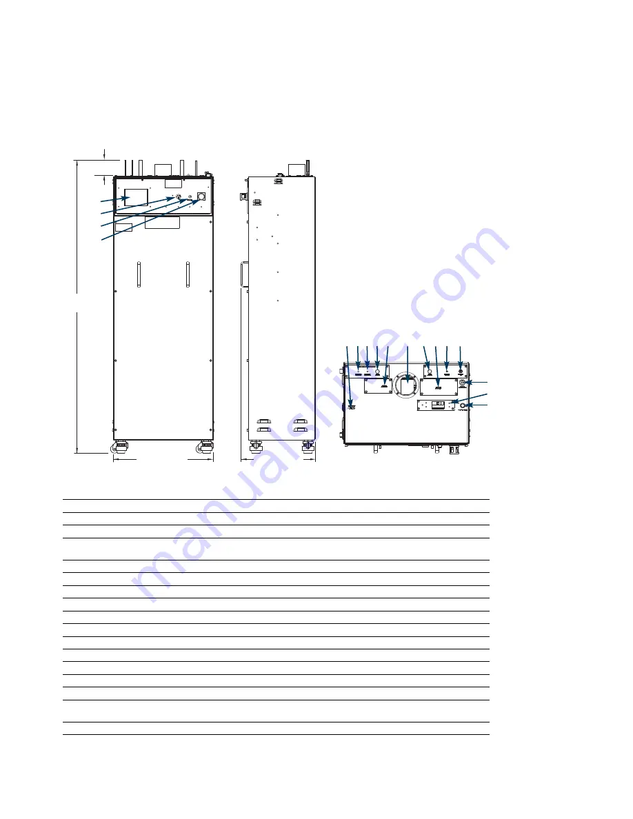
622 mm (24.50
″
)
Top view
454 mm (17.88
″
)
1831 mm
(72.08
″
)
Side view
System Connections
1
Touch screen
For system status and interface
2
Audible alarm
Audible warning informs of alarm condition
3
Start
Used to begin system operations and to clear alarms
4
EMO
When activated, power is removed from the cabinet. The system shuts down.
Front panel and controller remain powered.
5
Remote alarm interface
Allows for remote alarm input and output with female 15 pin DB connector
6
Regen gas input 1
Nitrogen input
7
Regen gas input 2
Hydrogen input
8
Process gas input
Inert gas (not purified)
9
Fire sensor located below cover
10
Exhaust vent
Allows ventilation
11
Process gas output
Outlet gas (purified)
12
Gas monitor located below cover
13
Regen gas vent
Exhausts regen gas
14
Instrument air
Supplies gas to the air-operated control valves
15
Reference
Atmospheric reference for the internal enclosure flow sensor
16
Circuit breaker
Provides additional electrical protection to the system and in some models
also acts as an ON/OFF switch for the system
17
A/C power input
Power connection
Enclosure Information
The ventilated enclosure is designed for indoor applications only. The enclosure has bolt down locations on
the bottom surface. The front panel is removable.
6
5
8
7
9
10 11
13 14
12
1
2
3
4
15
16
17
102 mm (4.03
″
)
Model EGPS12
Dimensional Information
Front view


