Testing Calibration and Relays
Entek IRD 6666 and 6667 Protection Monitors
43
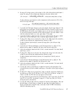
Repeat this process for channels 2–6.
The following table gives you example settings, inputs, and readings for several 6666
monitor configurations.
Note: Accuracy is ±2.5% of full scale.
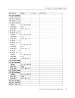
Signal Inputs for Testing a 6667 Monitor
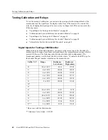
When testing any of the 6600 monitors, you must use the correct input. For the 6667, the
monitor expects a range of voltage corresponding to the thermocouple type which is preset
at the factory. The following table lists the available 6667 configurations. The monitor part
number is in the form 6667/AAAAAA where “A” indicates the thermocouple type for the
channel. The part number is labeled on the thermocouple conditioning unit (terminal block).
“B” config
“C” config
“N” config
Display units (UNITS 1)
°C
°C
°F
Full scale low
-20
0
0
Full scale high
200
250
300
Input resistance 50% full scale (ohms)
133.97
147.04
177.65
Front panel digital display
90
125
150
4–20 mA recorder terminals (mA)
12
12
12
Input resistance full scale high (ohms)
175.83
194.07
247.50
Front panel digital display
200
250
300
4–20 mA recorder terminals (mA)
20
20
20
Input resistance full scale low (ohms)
92.16
100.00
107.8
Front panel digital display
-20
0
0
4–20 mA recorder terminals (mA)
4
4
4
Suffix (“A”)
Thermocouple
Type
Range
T/C Voltage
Low (mV)
T/C Voltage
High (mV)
B
K
0 to 200°C
0.000
8.137
C
K
0 to 150°C
0.000
6.137
D
K
0 to 100°C
0.000
4.095
E
K
0 to 350°C
0.000
14.292
F
K
0 to 999°C
0.000
41.230
H
T
0 to 100°C
0.000
4.277
J
T
0 to 300°F
-0.676
6.647
P
J
0 to 300°F
-0.886
7.942


