background image

Mounting the Switch

Enterasys D-Series Hardware Installation Guide 2-13

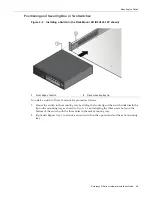
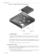
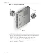
Figure 2-11  Installing the Switch On a Wall (shown with one D2-PWR supply)

1.

Ensure


that


you


have


appropriate


screws


for


securing


the


assembled


wall


mount


kit


to


your


wall


location.


These


four


screws


are


required


and


are


not


provided


in


the


wall


mount


kit.

2.

Mount


the


switch


on


the


front


side


of


the


wall


mount


kit


in


the


direction


shown,


aligning


the


three


screw


holes


on


the


bottom


of


the


unit


with


the


three


holes


in


the


wall


mount


tray.

3.

Using


the


screws


provided,


fasten


the


switch


to


the


wall


mounting


tray.

4.

Install


a


power


supply


by


sliding


it


under


the


flange


located


on


the


bottom


side


of


the


wall


mounting


tray.

1

Wall mounting screw holes (four)

7

Power supply (D2-PWR shown)

2

Switch mounting screw holes (three)

8

Power supply mounting flange

3

AC power receptacle

9

Power supply mounting bracket

4

Fan tab

10

Power supply hook & loop strap

5

Serial number access window

11

AC power cord

6

DC power cord

Note: 

Ensure that the D2 switch is secured to the wall mount tray in the position shown, with the 

back panel of the switch facing downward. The fan tab on the wall mount tray must face downward 
when the kit is installed on the wall.

Summary of Contents for D2G124-12

Page 1: ...Enterasys D Series Ethernet Switch D2G124 12 D2G124 12P Hardware Installation Guide P N 9034395 02 ...

Page 2: ......

Page 3: ...rks Inc All rights reserved Part Number 9034395 02 January 2009 ENTERASYS ENTERASYS NETWORKS ENTERASYS SECURE NETWORKS NETSIGHT ENTERASYS NETSIGHT SECURESTACK ENTERASYS SECURESTACK and any logos associated therewith are trademarks or registered trademarks of Enterasys Networks Inc in the United States and or other countries For a complete list of Enterasys trademarks see http www enterasys com com...

Page 4: ...ustry Canada Notice This digital apparatus does not exceed the class A limits for radio noise emissions from digital apparatus set out in the Radio Interference Regulations of the Canadian Department of Communications Le présent appareil numérique n émet pas de bruits radioélectriques dépassant les limites applicables aux appareils numériques de la class A prescrites dans le Règlement sur le broui...

Page 5: ...rical and electronic equipment is required and that this product was placed on the European market after August 13 2005 the date of enforcement for Directive 2002 96 EC 2 When this product has reached the end of its serviceable life it cannot be disposed of as unsorted municipal waste It must be collected and treated separately 3 It has been determined by the European Parliament that there are pot...

Page 6: ...ials in the parts is above the relevant threshold of the SJ T 11363 2006 standard ᇍ䫔ଂП᮹ⱘ᠔ଂѻક ᴀ㸼ᰒ ߃ կᑨ䫒ⱘ ᄤֵᙃѻકৃ㛑ࣙ 䖭ѯ 䋼DŽ ᛣ ᠔ଂѻકЁৃ㛑Ӯгৃ㛑ϡӮ ᠔ ᠔ ⱘ䚼ӊDŽ This table shows where these substances may be found in the supply chain of Enterasys electronic information products as of the date of sale of the enclosed product Note that some of the component types listed above may or may not be a part of the enclosed...

Page 7: ...fiber under normal conditions is 12 6 dBm or 55 x 10 6 watts Removing the optical connector from the transceiver allows laser radiation to emit directly from the optical port The maximum radiance from the optical port under worst case conditions is 0 8 W cm 2 or 8 x 10³ W m2 sr 1 Do not use optical instruments to view the laser output The use of optical instruments to view laser output increases e...

Page 8: ...ry Business Park London Road Newbury Berkshire RG14 2PZ England Conformance to Directive s Product Standards EC Directive 2004 108 EC EN 55022 2006 EN 55024 1998 EN 61000 3 2 2000 EN 61000 3 3 1995 EC Directive 2006 95 EC EN 60950 1 2001 EN 60825 1 1994 EN 60825 2 2004 Equipment Type Environment Information Technology Equipment for use in a Commercial or Light Industrial Environment Enterasys Netw...

Page 9: ...perability except to the extent expressly permitted by applicable law and to the extent the parties shall not be permitted by that applicable law such rights are expressly excluded Information necessary to achieve interoperability or correct errors is available from Enterasys upon request and upon payment of Enterasys applicable fee b Incorporate the Program in whole or in part in any other produc...

Page 10: ...ts showing i license fees due and paid and ii the use copying and deployment of the Program You also grant to Enterasys and its authorized representatives upon reasonable notice the right to audit and examine during Your normal business hours Your books records accounts and hardware devices upon which the Program may be deployed to verify compliance with this Agreement including the verification o...

Page 11: ...nforced to the maximum extent permissible Any such invalidity illegality or unenforceability in any jurisdiction shall not invalidate or render illegal or unenforceable such provision in any other jurisdiction 14 TERMINATION Enterasys may terminate this Agreement immediately upon Your breach of any of the terms and conditions of this Agreement Upon any such termination You shall immediately cease ...

Page 12: ...x ...

Page 13: ...the Assembled Kit Into a Rack 2 9 Connecting Power Console and Network Cables 2 9 Installing the Switch Under a Table 2 10 Installing the Switch on a Wall 2 12 Installing the Switch in the Lockbox and Mounting on a Wall 2 15 Installing the Switch in the Lockbox 2 15 Installing Power Supplies 2 16 Installing the D2 HIPWR POE in the Lockbox 2 18 Connecting Network Cabling and Attaching the Wire Reli...

Page 14: ...ure Power Supply edge of tray shown 2 7 2 7 Securing a Power Supply to the Rack Mount Tray edge of tray position shown 2 7 2 8 Rack Mount Switch Kit with Dual D2124 12Ps and Four D2 POE PWRs 2 9 2 9 Installing the Switch in the Table Mount Kit shown with one D2 PWR supply 2 10 2 10 Attaching the D2 HIPWR POE to the Table Mounting Tray 2 11 2 11 Installing the Switch On a Wall shown with one D2 PWR...

Page 15: ...ecifications A 4 A 6 MGBIC LC01 MGBIC MT01 Optical Specifications A 4 A 7 MGBIC LC01 MGBIC MT01 Operating Range A 4 A 8 MGBIC 02 Specifications A 5 A 9 MGBIC LC03 Optical Specifications A 5 A 10 MGBIC LC03 Operating Range A 5 A 11 MGBIC LC04 Optical Specifications A 5 A 12 MGBIC LC05 Optical Specifications A 6 A 13 MGBIC LC07 Optical Specifications A 6 A 14 MGBIC LC07 Operating Range A 6 A 15 MGBI...

Page 16: ...xiv ...

Page 17: ...ities of the D2 switch A general working knowledge of data communications networks is helpful Related Documents To configure the D2 switch refer to the Enterasys D Series CLI Reference Manuals can be accessed on the World Wide Web using the following URL http www enterasys com support manuals Electrical Hazard Only qualified personnel should install or service this unit Riesgo Electrico Nada mas p...

Page 18: ...n to any item of information that may be of special importance Caution Contains information essential to avoid damage to the equipment Precaución Contiene información esencial para prevenir dañar el equipo Achtung Verweißt auf wichtige Informationen zum Schutz gegen Beschädigungen Warning Warns against an action that could result in personal injury or death Advertencia Advierte contra una acción q...

Page 19: ...rk environment such as layout cable type other relevant environmental information Network load and frame size at the time of trouble if known The device history for example if you have returned the device before or if this is a recurring problem Any previous Return Material Authorization RMA numbers World Wide Web www enterasys com services support Phone 1 800 872 8440 toll free in U S and Canada ...

Page 20: ...Getting Help xviii About This Guide ...

Page 21: ...2G124 12 and D2G124 12P systems provide twelve copper 10 100 1000 RJ45 ports and two 1 Gigabit Small Form Factor Pluggable SFP fiber optic transceiver combo ports Power over Ethernet PoE is factory installed on the D2G124 12P A D2 switch can be placed on a table top as a freestanding unit installed into a standard 48 26 centimeter 19 inch rack mounted on a wall or mounted under a table The width o...

Page 22: ...er Supply 1 non PoE receptacle PWR1 A 9 RJ45 Port LEDs 3 Power Supply 2 non PoE receptacle PWR2 A 10 Power Supply 1 PWR1 LED 4 Console port RJ45 11 CPU system LED 5 Reset button 12 Power Supply 2 PoE receptacle PWR2 B 6 Power Supply 2 PWR2 LED 13 Power Supply 1 PoE receptacle PWR1 B 7 RJ45 ports 1 12 1 CPU system LED 3 RJ45 port LEDs ports 1 12 2 Power supply PWR1 and PWR2 LEDs 4 SFP combo port LE...

Page 23: ... the D2 switch D2 PWR a DC power supply capable of providing power to a fully loaded non PoE switch D2 PWR POE a DC power supply recommended for PoE power redundancy on six RJ45 ports D2 HIPWR POE an optional power combiner that provides a full 15 4 watts of PoE to all twelve RJ45 ports on the D2G124 12P Fan The D2 fan is designed to run extremely quiet and is only required to operate beyond tempe...

Page 24: ...gged into a D2G124 12P switch You can connect a single D2 HIPWR POE power combiner to your D2G124 12P switch or two D2 HIPWR POE power combiners for redundant PoE on all twelve front panel RJ45 ports Figure 1 3 shows the front panel LEDs and rear panel inputs of the D2 HIPWR POE power combiner Figure 1 3 D2 HIPWR POE PoE Power over Ethernet Support The D2G124 12P switch is 802 3af compliant This m...

Page 25: ... 802 3af specification which is part of the 802 3 suite of standards The switch is fully compliant with the IEEE 802 3af standard It supports the standard resistor based detection method as well as AC disconnect capability When operating at 40 C or less the switch supports an average of 8 3W PoE power per port It provides up to 15 4W for Class 3 support on any port up to a system maximum of 100 wa...

Page 26: ...PoE Power over Ethernet Support 1 6 Introduction ...

Page 27: ...he following table as a guideline Electrical Hazard Only qualified personnel should install or service this unit Riesgo Eléctrico Nada mas personal capacitado debe de instalar o darle servicio a esta unida Elektrischer Gefahrenhinweis Installationen oder Servicearbeiten sollten nur durch ausgebildetes und qualifiziertes Personal vorgenommen werden For information about Refer to page Unpacking the ...

Page 28: ...s Optional components shipped separately from the D2 switch include the following One or more additional power supply module s for redundancy either D2 PWR or D2 PWR POE D2 HIPWR POE power combiner One of the following installation kits Rack mount installation kit D2 RMT Table mount installation kit D2 TBL MNT Wall mount installation kit D2 WALL MNT Metal lockbox wall mount installation kit D2 LOC...

Page 29: ...ing on a Wall page 2 15 3 Connect power to the switch Refer to Connecting Power to the Switch on page 2 26 4 Connect to the console port Refer to Connecting to the Console Port on page 2 27 5 Connect to the network including installing optional SFPs Refer to Connecting to the Network on page 2 28 6 Install the optional plastic cover Refer to Installing the Optional Plastic Cover on page 2 33 7 Com...

Page 30: ...tch can be single or dual mounted in a standard EIA 310 D compliant 48 26 centimeter 19 inch equipment rack To mount one or two switches into a rack you must first install each switch into a rack mount kit as described in the following procedure You must provide the mounting hardware to attach the assembled kit to the rack rails Complete the following steps to install one or two switches in the ra...

Page 31: ...nt kit proceed as follows 1 Mount the switch in the mounting tray by sliding the front edge of the switch underneath the lip on the mounting tray as shown in Figure 2 4 and aligning the three screw holes on the bottom of the switch with the three holes in the rack mounting tray 2 Optional Repeat Step 1 to mount a second switch on the opposite side of the rack mounting tray 1 Front edge of switch 2...

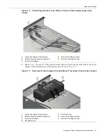
Page 32: ...e 2 8 Edge of Tray Installation Using one of the hook loop straps provided secure a power supply to one of the edge mounting positions on the rack mount kit as follows 1 Thread the strap through the mounting tray as shown in Figure 2 6 on page 2 7 and around one side of the power supply in the following order a Out through the first mounting hole closest to the top of the mounting tray b In throug...

Page 33: ...mounting tray Final placement is shown in Figure 2 7 Figure 2 7 Securing a Power Supply to the Rack Mount Tray edge of tray position shown 1 Top power supply mounting hole 4 Outer set of bridge anchors 2 Bottom power supply mounting hole 5 Inner set of bridge anchors 3 Hook loop straps 1 Top power supply mounting hole 5 AC power cord 2 Bottom power supply mounting hole 6 Outer set of bridge anchor...

Page 34: ...Under the power supply c Through the bridge anchor on the other side of the power supply d Wrap the ends of the strap over the top of the power supply and fasten securely 2 Repeat Step 1 with another hook loop strap to secure the other side of the power supply to the mounting tray Final placement is shown in Figure 2 8 on page 2 9 3 Plug the power cord from the power supply into the switch DC powe...

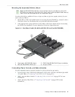
Page 35: ...onnecting Power Console and Network Cables Once the assembled rack mount kit is attached to your rack location proceed to Connect power to the switch es by plugging each AC power cord into a dedicated grounded AC outlet Refer to Connecting Power to the Switch on page 2 26 Attach console cable s Refer to Connecting to the Console Port on page 2 27 for more information Attach network cables Refer to...

Page 36: ...table location and rack mounting screws anchoring method that the installer selects for mounting the D2 switch must be capable of supporting 60 lbs 27 2kg Advertencia La ubicación de la mesa y el método de anclaje o los tornillos de montaje del estante que el instalador seleccione para montar el interruptor D2 deberán ser capaces de soportar un peso de 60 lbs 27 2 kg 1 Table mounting screw holes f...

Page 37: ... in the following order 1 Through the bridge anchor beside the power supply 2 Under the power supply 3 Out through the first mounting hole closest to the top of the power supply 4 In through the second mounting hole b Wrap the ends of the strap over the top of the power supply and fasten securely 5 Repeat Step 4 to secure the other end of the power supply to the mounting tray 6 Optional Repeat Ste...

Page 38: ... appropriate screws and the four screw holes in the corner edges of the table mounting tray attach the assembled kit underneath your desired table location Mount the assembled unit in place by positioning the screw holes over your installed table screws and pulling slightly forward on the unit 12 Attach network cables Refer to Connecting to the Network on page 2 28 for more information 13 Plug eac...

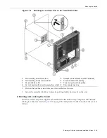
Page 39: ...t tray 3 Using the screws provided fasten the switch to the wall mounting tray 4 Install a power supply by sliding it under the flange located on the bottom side of the wall mounting tray 1 Wall mounting screw holes four 7 Power supply D2 PWR shown 2 Switch mounting screw holes three 8 Power supply mounting flange 3 AC power receptacle 9 Power supply mounting bracket 4 Fan tab 10 Power supply hook...

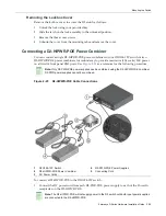
Page 40: ...PWR POE to the wall mounting tray refer to Figure 2 12 and proceed as follows Figure 2 12 Mounting the D2 HIPWR POE to the Wall Mounting Tray a With the hook and loop sides attached together peel back the adhesive covering on one side of each hook loop fastener and apply to opposite corners on the bottom of the D2 HIPWR POE b Once the hook loop fasteners are adhered to the bottom of the D2 HIPWR P...

Page 41: ...2 26 for information on redundancy and the initialization process 14 Optional If you have purchased an optional plastic cover attach it to the mounted D2 switch as described in Installing the Optional Plastic Cover page 2 33 Installing the Switch in the Lockbox and Mounting on a Wall To assemble the switch and other components in the D2 lockbox proceed as described in the following sections Instal...

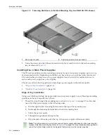
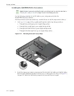
Page 42: ...st of the D2 components into the lockbox If you are installing the D2 HIPWR POE power combiner in the lockbox see Installing the D2 HIPWR POE in the Lockbox on page 2 18 To install power supplies into the lockbox 1 Using one of the hook loop straps provided complete the following steps to secure one end of the power supply in the position shown in Figure 2 14 on page 2 17 1 Mounting screws three 3...

Page 43: ...in Figure 2 14 on page 2 17 2 Plug the DC power cord from the power supply into the switch DC power receptacle that is appropriate for your type of power supply For the D2 PWR supply plug into the PWR1 A or PWR2 A receptacle For the D2 PWR POE supply plug into the PWR1 B or PWR2 B receptacle 3 Plug the AC cord into the power supply s AC receptacle 4 Optional If you have purchased a second power su...

Page 44: ...op right upper power supply bridge anchor b Through the bottom left lower power supply bridge anchor c Through the bottom right lower power supply bridge anchor Figure 2 15 Fastening the Hook Loop Straps 2 Install the upper power supply pressed against the left side of the lockbox and slightly higher than its normal installation position with it s power cord facing down as shown in Figure 2 16 on ...

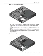
Page 45: ...hown in Figure 2 16 Fasten the two hook loop straps securely around the power supply 4 Attach the three prong end of the connecting cord to the Power1 B power input on your D2 switch 5 Thread the DC power cords from both power supplies and the connecting cord in between the D2 switch and the upper power supply and secure them in place with the hook loop strap as shown in Figure 2 17 Figure 2 17 Th...

Page 46: ...er cords through the hole in the bottom left of the lockbox if not mounting over a power outlet in between the D2 switch and upper power supply Use the hook loop strap securing the DC power cords and connecting cord to also secure the AC power cords Plug each AC cord into each power supply s AC receptacle 9 Seat the D2 HIPWR POE in the space between the power supplies and the D2 switch as shown in...

Page 47: ...ampering once cabling is connected to switch ports To attach the wire relief bracket to the lockbox tray 1 Attach network cables as shown in Figure 2 19 Refer to Connecting to the Network on page 2 28 for more information Figure 2 19 Attaching a Network Cable UTP cable to RJ45 port shown 2 Align the wire relief bracket with the flange and the two screw holes on the side of the lockbox tray as show...

Page 48: ...as demonstrated by Figure 2 21 on page 2 23 1 Screws provided 2 Wire relief bracket Note The D2 lockbox kit can only be mounted in a secure wall location The kit is not designed for table mounting or for use with a freestanding switch Caution The wall location and wall mounting screws anchoring method that the installer selects for mounting the D2 lockbox and switch assembly must be capable of sup...

Page 49: ... and Locking the Cover Once the switch and power supplies are assembled in the lockbox tray and power and network cabling is connected refer to Figure 2 22 on page 2 24 and proceed to attach and lock the cover as follows 1 Wall mounting screw holes four 5 Network wire relief bracket shown installed 2 Wall mounting screws not provided 6 AC power data outlet opening 3 AC power data outlet 7 Power su...

Page 50: ...unting tray 2 Slide the latch on the lock assembly to the position shown until it clicks into place 3 Lock the lockbox by turning the provided key in the lock counter clockwise 4 Insert the three cover screws provided in the positions shown and tighten securely 5 Return the lockbox key to a secure location 1 Cover locking tabs 3 Cover fastening screws three 2 Latch and lock assembly locking positi...

Page 51: ...edundancy to provide maximum 15 4 watts PoE power on all twelve front panel RJ45 ports Use Figure 2 23 as a reference for the following procedure Figure 2 23 D2 HIPWR POE Cable Connections To connect a D2 HIPWR POE to the D2G124 12P switch 1 Connect the DC power cord from each D2 PWR POE power supply to each of the Power In receptacles on the D2 HIPWR POE Note Only D2 PWR POE power supplies can be...

Page 52: ...m each power supply into each of the switch DC power receptacles that are appropriate for your type of power supplies For the D2 PWR supply plug into the PWR1 A and PWR2 A receptacles For the D2 PWR POE supply plug into the PWR1 B and PWR2 B receptacles For the D2 HIPWR POE power combiner attach cabling as instructed in Connecting a D2 HIPWR POE Power Combiner on page 2 25 2 Plug the AC cord into ...

Page 53: ...to the console port 1 Connect the RJ45 connector at one end of the cable to the RJ45 console port on the D2 switch 2 Plug the RJ45 connector at the other end of the cable into the RJ45 to DB9 adapter 3 Connect the RJ45 to DB9 adapter to the serial port on a terminal or a PC running terminal emulation software 4 Make sure the terminal emulation software is set as follows Select the appropriate seri...

Page 54: ... to RJ45 Ports RJ45 10000BASE TX front panel ports on the D2G124 12 and D2G124 12P switches support Auto MDIX which means that you can use straight through or crossover twisted pair cabling To connect twisted pair segments to the D2 refer to Figure 2 24 on page 2 29 and proceed as follows 1 Ensure that the device to be connected at the other end of the segment is powered on 2 Connect the twisted p...

Page 55: ...age xvii for details Repeat all steps above until all connections have been made Installing an Optional SFP This section describes how to install an SFP optical transceiver into combo SFP ports 11 and 12 on the D2G124 12 or D2G124 12P unit It is recommended that the options be installed first in a new installation Notes Each combo SFP port on the D2G124 12 and D2G124 12P supports the installation ...

Page 56: ... vean el puerto de la potencia optica la corriente debe ser removida del adaptador de la red Warnhinweis SFPs mit Fiber Optik Technologie benutzen Laser der Klasse 1 Benutzen sie keinesfalls optische Hilfsmittel um die Funktion des Lasers zu überprüfen Solche Hilfsmittel erhöhen die Gefahr von Sehschäden Wenn sie den optischen Port überprüfen möchten stellen Sie sicher dass die Komponente von der ...

Page 57: ...m the port slot without releasing it The SFP is released by pulling down on its wire handle Attempting to remove the SFP without releasing it can damage the SFP The SFP and its host D2 are sensitive to static discharges Use an antistatic wrist strap and observe all static precautions during this procedure Failure to do so could result in damaging the SFP or host D2 Always leave the SFP in the anti...

Page 58: ...nnect an LC or MT RJ cable connector to an SFP port connector 1 Remove the protective covers not shown from the uplink port SFP and from the connectors on each end of the cable 2 Insert the cable connector into the SFP connector until it clicks into place Caution Do not touch the ends of the fiber optic strands and do not let the ends come in contact with dust dirt or other contaminants Contaminat...

Page 59: ...port of the other device and the receive fiber optic strand on the D2 is connected to the transmit port of the other device 4 Repeat this procedure for other SFP ports if needed 5 If an SFP port is unused install a dust cover Installing the Optional Plastic Cover If you have purchased a D2 COVER W optional plastic cover you can install it over a freestanding or wall mounted switch as shown in Figu...

Page 60: ...el of the switch allowing access to the ports and network power and console cables If the switch is mounted on the wall as shown in Figure 2 11 on page 2 13 front panel LEDs will face up towards the ceiling and the open end of the cover will face down away from the ceiling allowing access to the ports and network power and console cables 2 Secure the cover in place When positioned securely mountin...

Page 61: ...or information on interpreting the power LEDs 3 Verify that the CPU LED blinks initially then becomes solid green 4 Make sure that the network devices connected to the switch ports are powered on then verify that each Link Activity LED is ON solid green or blinking green 5 At the device connected to the console port perform the following a Enter admin for Username b At the Password prompt press EN...

Page 62: ...rd and perform more involved management configurations on the D2 If you require assistance contact Enterasys Networks using one of the methods described in Getting Help on page xvii Note It is strongly recommended that you change the admin password from its default state of blank no password once the D2 switch becomes operational in your network For more information refer to the Enterasys D Series...

Page 63: ...EDs 3 1 Using the Password Reset Button 3 2 Resetting the D2 HIPWR POE 3 3 Electrical Hazard Only qualified personnel should install or service this unit Riesgo Eléctrico Nada mas personal capacitado debe de instalar o darle servicio a esta unida Elektrischer Gefahrenhinweis Installationen oder Servicearbeiten sollten nur durch ausgebildetes und qualifiziertes Personal vorgenommen werden Table 3 1...

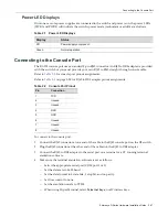
Page 64: ...sole port using the default password and assign a new password using the CLI 4 To access switch management from your local PC terminal or modem connection refer to the Enterasys D Series CLI Reference for instructions on how to log in and enter a new password If you require assistance contact Enterasys Networks using one of the methods described in Getting Help on page xvii Table 3 2 Power LED Def...

Page 65: ...t down in the event of an overload or short circuit To reset the D2 HIPWR POE Disconnect AC power to one of the power supplies Wait 30 seconds to allow the DC output voltage to decay enough to reset the D2 HIPWR POE before re applying AC power Remove and replace one of the D2 HIPWR POE s power input cables no minimum time required ...

Page 66: ...Resetting the D2 HIPWR POE 3 4 Troubleshooting ...

Page 67: ...pecifications A 4 Console Port Pinout Assignments A 7 Regulatory Compliance A 7 Table A 1 D2 Specifications Item Specification Ports RJ45 ports 1 through 12 Twelve 10BASE T 100BASE TX 1000BASE T compliant ports with auto sensing and auto negotiation via RJ45 connectors On the D2G124 12P these ports also support 802 3af PoE connections Combo SFP ports 11 and 12 Two ports that support optional Mini ...

Page 68: ...Power Requirements Input Voltage 100 to 240 VAC Power Consumption D2G124 12 30 W D2G124 12P 130W Input Frequency 50 60Hz Input Current D2G124 12 2 0A D2G124 12P 3 2A Thermal Output D2G124 12 110V 0 3A 102 39 BTUs hr D2G124 12P 110V 2 16A 443 69 BTUs hr Environmental Operating Temperature D2G124 12 0 C to 60 C 32 F to 140 F D2G124 12P 0 C to 50 C 32 F to 122 F Storage Temperature 40 C to 70 C 40 F ...

Page 69: ...e A 3 Power Supply Specifications Item Specification D2 PWR Input Frequency 50 to 60 Hz Input Voltage Current 100 240Vac 2 0A Output Voltage 19V 6 32A D2 PWR POE Input Frequency 47 to 63 Hz Input Voltage Current 100 240Vac 3 2A Output Voltage 50V 2 6 A max Table A 4 Recommended Torque Values by Screw Size Screw Size Torque in Pounds Bit Size English Metric 5 Nominal 5 N A N A 1 42 1 5 1 57 0 2 56 ...

Page 70: ... 1 LC fiber optic multimode port that is compliant with the 1000BASE SX standard and has an LC duplex style connector MGBIC LC04 1 LC fiber optic multimode port that is compliant with the 100BASE FX standard and has an LC connector MGBIC LC05 1 LC fiber optic single mode port that is compliant with the 100BASE FX standard and has an LC connector MGBIC LC07 1 LC fiber optic single mode port that is...

Page 71: ...dBm Link Power Budget1 Multimode Only 1 The maximum drive distance up to 2 km depends on the quality of the installed multimode fiber optic cable segment Use the Link Power Budget to calculate the maximum cable length of the attached segment The Link Power Budget must not exceed those specified in this table The MGBIC LC03 input power must not exceed 3 dBm Otherwise saturation could occur 10 5 dB ...

Page 72: ... The Link Power Budget must not exceed those specified in this table The MGBIC LC07 input power must not exceed 9 dBm Otherwise saturation could occur 28 dB Table A 14 MGBIC LC07 Operating Range Item 1550 nm Range 9 or 10 µm SMF N A 110 000 Meters Table A 15 MGBIC 08 Optical Specifications Item Transmit Power minimum 0 dBm min 2 dBm typical 5 dBm max Receive Sensitivity 24 dBm min 26 dBm typical M...

Page 73: ...Link Power Budget 8 5 dBm 8 5 dBm 10 5 dBm Table A 18 MGBIC LC09 Operating Range Item Modal Bandwidth 1300 nm Range 62 5 µm MMF 500 MHz km 2 550 Meters 50 µm MMF 400 MHz km 2 550 Meters 50 µm MMF 500 MHz km 2 550 Meters 10 µm SMF N A 2 10 000 Meters Table A 19 Compliance Standards Regulatory Compliance Standard Safety UL 60950 1 FDA 21 CFR 1040 10 and 1040 11 CAN CSA C22 2 No 60950 1 EN 60950 1 EN...

Page 74: ...Regulatory Compliance A 8 Specifications ...

Page 75: ...s for A 5 A 6 A 7 MGBIC MT01 specifications for A 4 A 5 Mounting options 2 4 N Network connecting to the 2 28 P Password reset button 3 2 Pinout assignments console port A 7 Plastic cover installation 2 33 PoE Power over Ethernet support 1 4 Power connecting to the switch 2 26 LED displays 2 27 supply specifications A 3 R Rack mounting 2 4 Regulatory compliance A 7 S SFP port connections 2 32 SFP ...

Page 76: ...Index 2 ...
Reviews: