


SecureStack C2 Installation Guide 1-1
1
Introduction
This
chapter
provides
a
functional
overview
of
a
Redundant
Power
System
(RPS).
RPS
Overview
An
RPS
(redundant
power
system)
consisting
of
a
C2RPS
‐
CHAS2
chassis
and
C2RPS
‐
PSM
power
supplies
is
a
simple
and
economical
solution
to
provide
backup
power
for
one
or
two
SecureStack
C2
Ethernet
switch
devices
(one
for
each
switch
device).
When
a
C2RPS
‐
PSM
is
connected
to
a
switch
device,
it
continuously
monitors
the
internal
power
supply
of
the
switch
device.
If
a
power
interruption
is
detected,
the
C2RPS
‐
PSM
is
automatically
triggered
to
provide
power
for
the
switch
device,
preventing
an
interruption
in
network
traffic.
The
end
result
is
a
more
reliable
network
infrastructure,
protecting
the
network
from
a
single
source
of
failure
from
a
network
device
power
supply.
Depending
on
your
system
requirements,
the
C2RPS
‐
CHAS2
chassis
can
consist
of
the
following
components
to
provide
redundant
power
for
one
or
two
switch
devices:
•
One
C2RPS
‐
CHAS2
chassis
•
One
or
two
C2RPS
‐
PSMs
(one
per
SecureStack
switch
device)
•
One
or
two
AC
power
cords
(one
per
C2RPS
‐
PSM)
•
One
or
two
C2RPS
‐
PSM
Cables
(one
per
C2RPS
‐
PSM)
For information about...
Refer to page...
RPS Overview
1-1
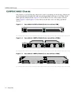
C2RPS-CHAS2 Chassis
1-2
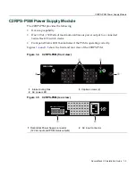
C2RPS-PSM Power Supply Module
1-3
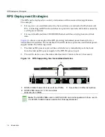
RPS Deployment Strategies
1-4
Getting Help
1-5
Note:
The chassis is shipped without a PSM. The PSMs are ordered separately. Each
PSM is shipped with an interconnecting C2RPS-PSM Cable and an AC power cord
.
Summary of Contents for SecureStack C2 C2RPS-CHAS2
Page 2: ......
Page 10: ...viii...
Page 16: ...Conventions Used in This Guide xiv About This Guide...
Page 22: ...Getting Help 1 6 Introduction...
Page 30: ...Connecting the PSM Cables and AC Power Cords 2 8 Installation...