
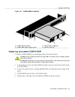


Installing C2RPS-CHAS2 into the Rack
2-4 Installation
To
install
a
PSM,
proceed
as
follows:
1.
Align
the
PSM
with
the
slot,
then
slide
the
PSM
forward
until
its
front
panel
is
flush
against
the
chassis
front
panel.
2.
Fasten
the
PSM
to
the
chassis
using
the
captive
screws.
3.
Perform
steps
1
and
2
for
each
PSM
being
replaced.
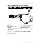
When
completed,
proceed
to
“
Connecting
the
PSM
Cables
and
AC
Power
Cords
”
on
page 2
‐
6.
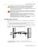
Installing C2RPS-CHAS2 into the Rack
To
install
the
chassis
into
a
19
‐
inch
(48.3
‐
cm)
rack,
you
need
four
user
‐
supplied
screws
to
fasten
the
chassis
to
the
rack
rails.
After
installing
the
PSM(s)
as
described
back
in
“
Installing
C2RPS
‐
PSMs
”
on
page 2
‐
2,
rack
mount
the
chassis
as
follows:
1.
Refer
to
the
installation
guidelines
(“
Guidelines
for
Rackmount
Installation
”
on
page 2
‐
4).
2.
Install
the
chassis
into
the
rack
(“
Rack
Mounting
the
Chassis
”
on
page 2
‐
5).
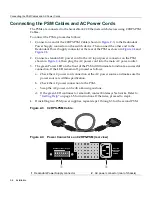
3.
Connect
the
PSM
cables
and
AC
power
cords
(“
Connecting
the
PSM
Cables
and
AC
Power
Cords
”
on
page 2
‐
6).
Guidelines for Rackmount Installation
The
installation
site
must
be
within
reach
of
the
network
cabling
and
meet
the
requirements
listed
below:
•
Chassis
placement
close
enough
to
connect
the
2
‐
meter
(6.6
‐
foot)
AC
power
cords
from
the
PSMs
to
the
AC
power
source.
•
Up
to
two
three
‐
pronged
power
receptacles
capable
of
delivering
the
current
and
voltage
specified
in
“
C2RPS
‐
PSM
Specifications
”
on
page A
‐
2.
Up
to
two
AC
outlets
on
independently
‐
fused
circuits
must
be
within
182 centimeters
(6 feet)
from
the
installation
site.
If
there
is
an
AC
power
source
failure,
this
will
prevent
the
powering
down
of
PSMs
due
to
a
single
source
power
failure.
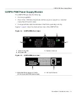
•
Power
cords
and
type
of
outlet
are
dependent
on
the
country.
In
the
United
States,
one
power
cord
with
an
NEMA
5
‐
15P
plug
is
provided
with
each
C2RPS
‐
PSM.
•
An
ambient
temperature
of
between
5
°
C
(41
°
F)
and
40
°
C
(104
°
F)
must
be
maintained
at
the
installation
site
with
fluctuations
of
less
than
10
°
C
(18
°
F)
per
hour.
Note:
If you plan to remove and not replace a C2RPS-PSM, immediately reinstall
coverplates over any empty power supply slots to prevent EMI leakage from the chassis.
Summary of Contents for SecureStack C2 C2RPS-CHAS2
Page 2: ......
Page 10: ...viii...
Page 16: ...Conventions Used in This Guide xiv About This Guide...
Page 22: ...Getting Help 1 6 Introduction...
Page 30: ...Connecting the PSM Cables and AC Power Cords 2 8 Installation...


