19
CAN
Units
ENTIA
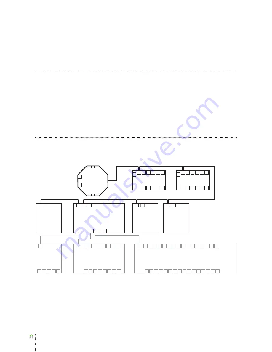
living CAN (eBUS) controllers, such as Main Controller EL-M01, Main Controller EL-M01a,
Room Controller EL-R02, DALI Converter EL-CD01, MODBUS Converter EL-CA01 and Sens
Controller EL-S01 have to be connected as shown in the block diagram below. Note that on
the block diagram below, the CAN elements and wiring is highlighted. The order in which
CAN devices are interconnected is of no consequence (e.g. we could start with a Room
Controller instead of the Main Controller). Multiple Main Controllers can be connected in
one eBUS circuit, if required (e.g. in case of more than 64 power outputs).
Sens
Controller
EL-S01
Room Controller
EL-R02
DALI Converter
EL-CD01
Power Dimmer
EL-D01
MODBUS
Converter
EL-CA01
Power Supply
EL-PS01
Main Controller EL-M01
Power Expander EL-E801
Power Expander EL-E1601
Room Controller
EL-R02
2x0.75
eBUS (CAN) J(Y)-ST-Y
2 x 2 x 0,8 J(Y)-STY
2 x 2 x 0,8 J(Y)-STY
2 x 2 x 0,8 J(Y)-STY
2 x 2 x 0,8 J(Y)-STY
2 x 2 x 0,8 J(Y)-STY
Summary of Contents for EL-CA01
Page 1: ...1 S M A R T F O R Y O U R H O M E I N S T A L L A T I O N M A N U A L ...
Page 2: ...2 INSTALATION MANUAL ...
Page 4: ...4 Lighting On Off ...
Page 6: ...6 Lighting Dimm ...
Page 8: ...8 Lighting DALI ...
Page 10: ...10 Heating Cooling Valves ...
Page 12: ...12 Heating Cooling Fan Coils ...
Page 14: ...14 Shading Shades Blinds ...
Page 16: ...16 Air Conditioning IR ...
Page 18: ...18 Air Conditioning MODBUS ...
Page 20: ...20 CAN Units ...
Page 22: ...22 Buttons Switches Power Expander connect ...


