background image

37

IP2132EN - 2015-03-09

Operating instructions

General safety precautions for the user

DET

A

CH AND DELIVER T

O THE CUST

OMER

These precautions are an 
integral and essential part of 

the product and must be supplied 
to the user.
Read them carefully since they 
contain important information on 
safe installation, use and mainte-
nance.
These instructions must be kept 
and forwarded to all possible future users of the system. 
This product must only be used for the specific purpose for which it was 
designed. Any other use is to be considered improper and therefore 
dangerous. 
The manufacturer cannot be held responsible for any damage caused 
by improper, incorrect or unreasonable use.
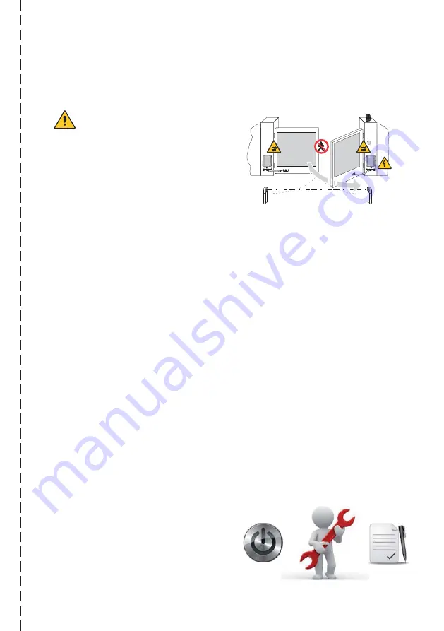
Avoid operating in the proximity of the hinges or moving mechanical 
parts.  Do not enter within the operating range of the motorised door 
or gate while it is moving.
Do not obstruct the motion of the motorised door or gate, as this may 
cause a dangerous situation. 
The motorised door or gate may be used by children over the age of 8 
and by people with reduced physical, sensorial or mental abilities, or 
lack of experience or knowledge, as long as they are properly supervised 
or have been instructed in the safe use of the device and the relative 
hazards.
Do not allow children to play or stay within the operating range of the 
motorised door or gate.
Keep remote controls and/or any other command devices out of the 
reach of children, to avoid any accidental activation of the motorised 
door or gate.
In the event of a product fault or malfunction, turn off the power supply 
switch. Do not attempt to repair or intervene directly, and contact only 
qualified personnel.
Failure to comply with the above may 
cause a dangerous situation.
Any repair or technical intervention 
must  be  carried  out  by  qualified 
personnel.

Summary of Contents for Ditec FACIL

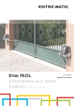
Page 1: ...Ditec FACIL www ditecentrematic com 3...

Page 2: ...2 3 Italiano 3 English 23 Fran ais 43 Deutsch 63 Espa ol 83 Portugu s...

Page 3: ...Ditec FACIL Automazione per cancelli battenti Istruzioni originali www ditecentrematic com IP2132IT Manuale Tecnico...

Page 4: ...o 9 5 Dimensioni 10 6 Installazione 11 6 1 Controlli preliminari 11 6 2 Fissaggio staffe 12 6 3 Installazione motoriduttore 13 6 4 Installazione e regolazione dei necorsa 14 7 Collegamenti elettrici 1...

Page 5: ...igore i criteri della Buona Tecnica l ambiente di installazione la logica di funzionamento del sistema e le forze sviluppate dalla porta o cancello motorizzati I dispositivi di sicurezza devono proteg...

Page 6: ...h sotto sorveglianza oppure dopo che le stesse abbiano ricevuto istruzioni relative all uso sicuro dell apparecchio e alla comprensione dei pericoli ad esso inerenti I bambini devono essere sorvegliat...

Page 7: ...lla Direttiva compatibilit elettromagnetica 2004 108 CE la documentazione tecnica conforme all allegato VII B della Direttiva 2006 42 CE la documentazione tecnica viene gestita da Marco Pietro Zini co...

Page 8: ...nta elementi variabili quali attriti bilanciature e condizioni ambientali che possono modi care in maniera sostanziale sia la durata che la qualit di funzio namento dell ingresso automatico o di parte...

Page 9: ...e FACIL3EH Motoriduttore con quadro elettronico incorporato 6 XEL2 LAB4 Fotocellule Fotocellule IP55 A Scatola di derivazione non di nostra fornitura Collegare l alimentazione ad un interruttore onnip...

Page 10: ...10 IP2132IT 2015 03 09 5 Dimensioni 333 188 285 285...

Page 11: ...ione 6 1 Controlli preliminari Controllare che la struttura del cancello sia robusta e che i cardini siano lubri cati Prevedere una battuta d arresto in apertura e in chiusura Veri care le misure di i...

Page 12: ...2 Fissaggio staffe Fissare in modo robusto e stabile la piastra di fissaggio 8 al pilastro del cancello e la staffa di fissaggio del braccio 13 sull anta come indicato in figura 44 65 76 11 5 8 5 43 3...

Page 13: ...duttore vedi istruzioni d uso 7 9 BOXFC1 E2HFC 8 Fissare i bracci snodati e la staffa di fissaggio del braccio 13 come indicato in figura Gli snodi dei bracci vanno lubrificati e le viti vanno strette...

Page 14: ...uto Serrare in questa posizione l anello portacamme tramite la vite 4 ATTENZIONE veri care che tra il motoriduttore e le camme del necorsa ci sia una distanza di almeno 1 mm Fig 2 3 Con cancello in po...

Page 15: ...orsetti L marrone N blu giallo verde presenti all interno dell automazione Bloccare il cavo mediante l apposito fermacavi e sguainarlo solamente in corrispondenza del morsetto Il collegamento alla ret...

Page 16: ...le seguenti operazioni e veri che ogni 6 mesi in base all intensit di utilizzo dell au tomazione Togliere alimentazione 230 V e batterie se presenti Pulire e lubri care con grasso neutro i perni di r...

Page 17: ...on entrare nel raggio di azione della porta o cancello motorizzati mentre sono in movimento Non opporsi al moto della porta o cancello motorizzati poich possono causare situazioni di pericolo La porta...

Page 18: ...ffet tuare da personale quali cato la manutenzione periodica della porta o cancello motorizzati In particolare si raccomanda la veri ca periodica del corretto funzionamento di tutti i dispositivi di s...

Page 19: ...are il cancello chiudere lo sportello girare la chiave in senso antiorario e togliere la chiave NOTA per disalimentare l automazione si deve togliere l alimentazione e scollegare le batterie se presen...

Page 20: ...rma tecnico Firma committente Timbro installatore Operatore Data intervento Firma tecnico Firma committente Intervento effettuato Intervento effettuato Entrematic Group AB Lodjursgatan 10 SE 261 44 La...

Page 21: ...no stati redatti con la massima cura Entrematic Group AB non pu assumersi alcuna responsabilit per danni causati da eventuali errori o omissioni in questa pubblicazione Ci riserviamo il diritto di app...

Page 22: ...IP2132IT 2015 03 09 Entrematic Group AB Lodjursgatan 10 SE 261 44 Landskrona Sweden www ditecentrematic com...

Page 23: ...Ditec FACIL Swing gates automation Original instructions www ditecentrematic com IP2132EN Technical Manual...

Page 24: ...installation 29 5 Dimensions 30 6 Installation 31 6 1 Preliminary checks 31 6 2 Bracket fastening 32 6 3 Geared motor installation 33 6 4 Limit switch installation and adjustment 34 7 Electrical conn...

Page 25: ...y edges emergency stops etc must be installed taking into account applicable laws and directives Good Working Methods installation premises system operating logic and the forces developed by the motor...

Page 26: ...hysical sensorial or mental abilities or lack of experience or knowledge as long as they are properly supervised or have been instructed in the safe use of the device and the relative hazards Children...

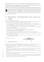
Page 27: ...2004 108 EC conforms to the R TTE Directive 1999 5 EC the technical documentation conforms to Annex VII B of the Directive 2006 42 EC the technical documentation is managed by Marco Pietro Zini with...

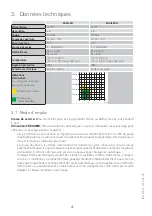
Page 28: ...ny special maintenance The actual performance characteristics of each automatic access may be affected by independent variables such as friction balancing and environmental factors all of which may su...

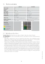
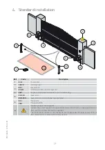
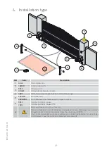
Page 29: ...itoring 5 FACIL3H Gearmotor FACIL3EH Gearmotor and control panel incorporated 6 XEL2 LAB4 Photocells Photocells IP55 A Connector block not supplied Connect the power supply to an approved omnipolar sw...

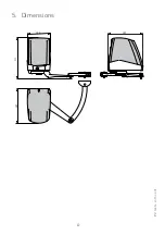
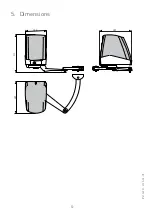
Page 30: ...30 IP2132EN 2015 03 09 5 Dimensions 333 188 285 285...

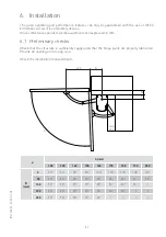
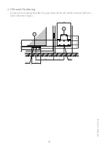
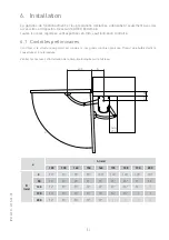
Page 31: ...are expressed in mm 6 1 Preliminary checks Check that the structure is suf ciently rugged and that the hinge pivots are properly lubricated Provide an opening and closing stop Check the installation m...

Page 32: ...32EN 2015 03 09 6 2 Bracket fastening Securely fix the fastening plate 8 to the gate pillar and the arm retention bracket 13 to the leaf as indicated in figure 44 65 76 11 5 8 5 43 31 400 8 5 100 160...

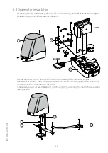
Page 33: ...use instructions 7 9 BOXFC1 E2HFC 8 Fix the articulated arms and the arm retention bracket 13 as indicated in figure The arm articulations must be lubricated and the screws sufficiently tightened so t...

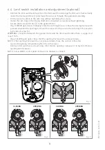
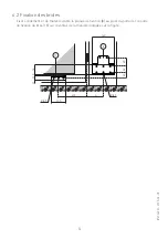
Page 34: ...roswitch released Firmly secure the cam ring in this position by means of screw 4 WARNING check that between the geared motor and the limit switch cams there is a gap of at least 1 mm Fig 2 3 With gat...

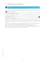
Page 35: ...cable and connect it to the terminals L brown N blue yellow green in the automation Secure the cable using a special cable clamp and remove the sheath only where the clamp is Connection to the mains...

Page 36: ...s according to intensity of use of the automation Without 230 V power supply and batteries if present Clean and lubricate the gate s rotation pins and hinges with neutral grease Check the resistance o...

Page 37: ...f the motorised door or gate while it is moving Do not obstruct the motion of the motorised door or gate as this may cause a dangerous situation The motorised door or gate may be used by children over...

Page 38: ...nance on the motorised door or gate In particular regular checks are recommended in order to verify that the safety devices are operating correctly All installation maintenance and repair work must be...

Page 39: ...k the gate again close the hatch turn the key anticlockwise and remove the key NOTE to turn off the automation the power supply and batteries if present must be disconnected WARNING when the hatch is...

Page 40: ...www ditecentrematic com Installer s stamp Operator Date of intervention Technician s signature Customer s signature Installer s stamp Operator Date of intervention Technician s signature Customer s s...

Page 41: ...this publication have been drawn up with the greatest care Entrematic Group AB cannot be held responsible in any way for any damage caused by mistakes or omissions We reserve the right to make changes...

Page 42: ...IP2132EN 2015 03 09 Entrematic Group AB Lodjursgatan 10 SE 261 44 Landskrona Sweden www ditecentrematic com...

Page 43: ...Ditec FACIL Automatisme pour portes battant Instructions originales www ditecentrematic com IP2132FR Manuel Technique...

Page 44: ...0 6 Installation 11 6 1 Contr les pr liminaires 11 6 2 Fixation des brides 12 6 3 Installation motor ducteur 13 6 4 Installation et r glage des ns de course 14 7 Raccordements lectriques 15 8 Plan d e...

Page 45: ...es directives en vigueur les crit res de la bonne technique le milieu o a lieu l installation la logique de fonctionnement du syst me et les forces d velopp es par la porte ou le portail motoris Les d...

Page 46: ...ances ou d exp rience sous r serve d une surveillance appropri e ou apr s avoir re u des instructions relatives une utilisation en toute s curit de l appareil et la compr hension des dangers qu il com...

Page 47: ...ive Compatibilit lectromagn tique 2004 108 CE est conforme la Directive R TTE 1999 5 CE la documentation technique est conforme l annexe VII B de la Directive 2006 42 CE la documentation technique est...

Page 48: ...aque cas sp ci que Chaque entr e automatique pr sente des l ments variables comme frottements compen sations et conditions environnementales pouvant modi er fondamentalement aussi bien la dur e que la...

Page 49: ...EH Motor ducteur avec tableau lectronique incorpor 6 XEL2 LAB4 Cellules photo lectriques Cellules photo lectriques IP55 A Bo te de d rivation n est pas fournie Relier l alimentation un interrupteur om...

Page 50: ...50 IP2132FR 2015 03 09 5 Dimensions 333 188 285 285...

Page 51: ...ontraire 6 1 Contr les pr liminaires Contr ler si la structure du portail est solide et si les gonds sont bien graiss s Pr voir une but e d arr t l ouverture et la fermeture V rifier les mesures d ins...

Page 52: ...ion des brides Fixer solidement et de mani re stable la plaque de fixation 8 au pilier du portail et la patte de fixation du bras 13 sur le vantail de la mani re indiqu e sur la figure 44 65 76 11 5 8...

Page 53: ...or ducteur voir le mode d emploi 7 9 BOXFC1 E2HFC 8 Fixer les bras articul s et la patte de fixation 13 de la mani re indiqu e sur la figure Les articulations des bras doivent tre graiss es et les vis...

Page 54: ...te position l anneau porte cames avec la vis 4 ATTENTION v ri er si entre le motor ducteur et les cames du n de course il y a une distance d au moins 1 mm Fig 2 3 Portail en position ouverte v ri er q...

Page 55: ...corder aux bornes L marron N bleu T jaune vert l int rieur de l automatisme Bloquer le c ble l aide du serre c bles et le d pouiller seulement au niveau de la borne Le raccordement au r seau de distri...

Page 56: ...ctionnement du syst me de d verrouillage Contr ler le fonctionnement des batteries en continuit si pr sent le tableau lectrique VIVAH ou E2HFC avec kit batteries en coupant l alimentation et en effect...

Page 57: ...i res ou des organes m caniques en mouvement Ne jamais se mettre dans le rayon d action de la porte ou du portail motoris e pendant qu il elle est en mouvement Ne jamais s opposer au mouvement de la p...

Page 58: ...ement les indications du constructeur en faisant effec tuer p riodiquement par un personnel quali l entretien p riodique de la porte ou du portail motoris e En particulier il est conseill de faire v r...

Page 59: ...illes d une montre et enlever la cl REMARQUE pour couper l alimentation de l automation il faut couper l alimentation et enlever les batteries si pr sentes ATTENTION lorsque la porte est ferm e mais l...

Page 60: ...eden www ditecentrematic com Cachet installateur Op rateur Date intervention Signature technicien Signature client Cachet installateur Op rateur Date intervention Signature technicien Signature client...

Page 61: ...rand soin cependant Entrematic Group AB d cline toute responsabilit en cas de dommages caus s par d ventuelles erreurs ou omissions pr sentes dans ce document Nous nous r servons le droit d apporter d...

Page 62: ...IP2132FR 2015 03 09 Entrematic Group AB Lodjursgatan 10 SE 261 44 Landskrona Sweden www ditecentrematic com...

Page 63: ...Ditec FACIL Drehtorantrieb Originalsprachlichen Anweisungen www ditecentrematic com IP2132DE Technisches Handbuch...

Page 64: ...sungen 70 6 Installation 71 6 1 Einleitende Kontrollen 71 6 2 Befestigung der Halterungen 72 6 3 Installation des Getriebemotors 73 6 4 Montage und Einstellung der Endschalter 74 7 Elektrische Anschl...

Page 65: ...ie geltenden Normen und Richtlinien die Montageanweisung die Montageumgebung die Betriebslogik des Systems und die von der motorisierten T r oder Tor entwickelten Kr fte Die Sicherheitseinrichtungen d...

Page 66: ...lichen Kenntnisse verwendet werden jedoch nur unter Aufsicht oder nach dem sie ber die sichere Verwendung der Einrichtung und den damit verbundenen Risiken aufgekl rt wurden Kinder m ssen beaufsichtig...

Page 67: ...ungsrichtlinie 2006 95 EG entspricht der EMV Richtlinie 2004 108 EG entspricht der Richtlinie R TTE 1999 5 EG entspricht die technischen Unterlagen dem Anhang VII B der Richtlinie 2006 42 EG entsprech...

Page 68: ...da au erordentliche Wartungsarbeiten erforderlich sind Jede Toranlage weist ver nderliche Faktoren auf Reibung Ausgleichvorg nge sowie Umweltbe dingungen k nnen sowohl die Lebensdauer als auch die Qu...

Page 69: ...Getriebemotor FACIL3EH Getriebemotor mit eingebaute Steuerung 6 XEL2 LAB4 Lichtschranken Lichtschranken IP55 A Abzweigdose nicht im Lieferumfang Die Stromversorgung an einen allpoligen Schalter mit ei...

Page 70: ...70 IP2132DE 2015 03 09 5 Abmessungen 333 188 285 285...

Page 71: ...en 6 1 Einleitende Kontrollen Pr fen Sie ob die Torkonstruktion stabil und leichtg ngig ist F r die Endlagen m ssen mecha nische Toranschl ge bzw Endschalter vorhanden sein Die Montagema e pr fen wie...

Page 72: ...festigung der Halterungen Befestigen Sie auf robuste und stabile Weise die Befestigungsplatte 8 am Torpfosten und den Befestigungsb gel des Arms 13 am Tor wie in Abbildung angegeben 44 65 76 11 5 8 5...

Page 73: ...bemotor siehe Gebrauchsanleitung 7 9 BOXFC1 E2HFC 8 Befestigen Sie die Gelenkarme und den Befestigungsb gel des Arms 13 wie in Abbildung gezeigt Die Gelenkarme m ssen geschmiert und die Schrauben so a...

Page 74: ...ube 4 befestigt ACHTUNG es ist darauf zu achten dass der Getriebemotor und die Nocken des Endanschlags mindestens 1 mm Abstand voneinander haben Abb 2 3 Bei offenem Dreh oder Schwingtor mu gepr ft wer...

Page 75: ...raun N blau gelb gr n anschlie en die sich im Antrieb be nden Das Kabel mit dem entsprechenden Kabelbinder befestigen und nur auf Klemmenh he abziehen Der Anschluss an das Stromnetz im Au enbereich de...

Page 76: ...ems berpr fen Den Akku Dauer betrieb pr fen wenn die elektronische Steuerung VIVAH oder E2HFC mit Akkusatz vorhanden wobei die Stromversorgung abgeschaltet wird und hintereinander ei nige Man ver durc...

Page 77: ...hrend der Bewegung nicht in Arbeitsbereich der motorisierten T r oder des Tors auf Die Bewegung der motorisierten T r oder des Tors nicht behindern um Gefahrensituationen zu vermeiden Die motorisiert...

Page 78: ...erten T r oder am Tor durch Fachpersonal nach Vorgabe des Herstellers aus gef hrt werden Insbesondere wird die regelm ige berpr fung der Betriebst chtigkeit aller Sicherheitseinrichtungen empfohlen Di...

Page 79: ...appe schlie en den Schl ssel entgegen dem Uhrzeigersinn drehen und den Schl ssel herausziehen ANMERKUNG zum Trennen des Antriebs muss die Stromversorgung unterbrochen und die Akkus wenn vorhanden getr...

Page 80: ...des Installateurs Bediener Datum des Eingriffs Unterschrift des Technikers Unterschrift des Auftraggebers Stempel des Installateurs Bediener Datum des Eingriffs Unterschrift des Technikers Unterschrif...

Page 81: ...no stati redatti con la massima cura Entrematic Group AB non pu assumersi alcuna responsabilit per danni causati da eventuali errori o omissioni in questa pubblicazione Ci riserviamo il diritto di app...

Page 82: ...IP2132DE 2015 03 09 Entrematic Group AB Lodjursgatan 10 SE 261 44 Landskrona Sweden www ditecentrematic com...

Page 83: ...Ditec FACIL Automatizaci n para cancelas batientes Instrucciones originales www ditecentrematic com IP2132ES Manual t cnico...

Page 84: ...talaci n 91 6 1 Comprobaciones preliminares 91 6 2 Fijaci n de los estribos 92 6 3 Instalaci n del motorreductor 93 6 4 Instalaci n y ajuste de los microinterruptores 94 7 Conexiones el ctricas 95 8 P...

Page 85: ...iendo en cuenta las normativas y directivas vigentes rigor en la buena t cnica el lugar de instalaci n la l gica de funcionamiento del sistema y las fuerzas creadas por la puerta o la cancela motoriza...

Page 86: ...e haber recibido instrucciones relativas al uso seguro del aparato y a la comprensi n de los peligros rela cionados con el mismo Hay que vigilar a los ni os para asegurarse de que no jueguen con el ap...

Page 87: ...forme a la Directiva R TTE 1999 5 CE la documentaci n t cnica es conforme al anexo VII B de la Directiva 2006 42 CE la documentaci n t cnica es gestionada por Marco Pietro Zini con sede en Via Mons Ba...

Page 88: ...acceso autom tico presenta elementos variables como roces compensaciones y condiciones ambientales que pueden alterar sustancialmente tanto la duraci n como la calidad de funcionamiento del acceso au...

Page 89: ...CIL3EH Motorreductor con cuadro electr nico incorporado 6 XEL2 LAB4 Fotoc lulas Fotoc lulas IP55 A Caja de derivaci n no incluida Conecte la alimentaci n a un interruptor bipolar de tipo homologado co...

Page 90: ...90 IP2132ES 2015 03 09 5 Dimensiones 333 188 285 285...

Page 91: ...lo contrario 6 1 Comprobaciones preliminares Controlar que la estructura sea fuerte y que los goznes est n lubricados Prever un tope de parada en la abertura y en el cierre Compruebe las medidas de i...

Page 92: ...Fijaci n de los estribos Fije de manera estable y resistente la placa de fijaci n 8 al pilar de la cancela y la abrazadera de fijaci n del brazo 13 a la hoja como indica la figura 44 65 76 11 5 8 5 43...

Page 93: ...s de uso 7 9 BOXFC1 E2HFC 8 Fije los brazos articulados y la abrazadera de fijaci n del brazo 13 como indica la figura Las articulaciones de los brazos deben lubricarse y los tornillos deben apretarse...

Page 94: ...anillo portalevas por medio del tornillo 4 ATENCI N veri car si entre el motorreductor y las levas del nal de carrera existe una distancia de por lo menos 1 mm Fig 2 3 Con la cancela en posici n de ab...

Page 95: ...L marr n N azul amarillo verde presentes en el interior del automatismo Bloquee el cable mediante el correspondiente sujetacables y p lelo solamente a la altura del borne La conexi n a la red de distr...

Page 96: ...a de desbloqueo funciona correctamente Verifique el funcionamiento de las bater as en continuidad en caso de tener cuadro elec tr nico VIVAH E2HFC con kit de bater as BATK2 quitando la alimentaci n y...

Page 97: ...erta o la cancela motorizadas mientras est n en movimiento No obstaculice el movimiento de la puerta o la cancela motorizadas ya que se podr an originar situaciones de peligro La puerta o la cancela m...

Page 98: ...cado las operaciones de mantenimiento peri dico de la puerta o la cancela motorizadas Se recomienda en particular comprobar peri dicamente el funcionamiento de todos los dispositivos de seguridad del...

Page 99: ...entido contrario al de las agujas del reloj y quite la llave NOTA para desactivar la alimentaci n del automatismo hay que quitar la alimentaci n y desco nectar las bater as si las hay ATENCI N cuando...

Page 100: ...a Sweden www ditecentrematic com Sello instalador Operador Fecha intervenci n Firma t cnico Firma ordenante Sello instalador Operador Fecha intervenci n Firma t cnico Firma ordenante Intervenci n efec...

Page 101: ...ado con la m xima atenci n Entrematic Group AB no puede asumir ninguna responsabilidad por da os causados por eventuales errores u omisiones en esta publicaci n Nos reservamos el derecho de aportar ev...

Page 102: ...IP2132ES 2015 03 09 Entrematic Group AB Lodjursgatan 10 SE 261 44 Landskrona Sweden www ditecentrematic com...

Page 103: ...Ditec FACIL Automatismo para port es de batente Instru es originais www ditecentrematic com IP2132PT Manual t cnico...

Page 104: ...la o tipo 109 5 Dimens es 110 6 Instala o 111 6 1 Controlos pr vios 111 6 2 Fixa o dos suportes 112 6 3 Instala o do moto redutor 113 6 4 Instala o e regula o dos ns de curso 114 7 Liga es el tricas 1...

Page 105: ...os crit rios da Boa T cnica o ambiente de instala o a l gica de funcionamento do sistema e as for as desenvolvidas pela porta ou port o motorizados Os dispositivos de seguran a devem proteger as even...

Page 106: ...u ap s receberem instru es relativas utiliza o segura do aparelho e compreens o dos perigos inerentes a ele As crian as devem ser supervisionadas para garantir que n o brinquem com o aparelho e para e...

Page 107: ...tiva 2006 42 CE a documenta o t cnica gerida por Marco Pietro Zini com sede em Via Mons Ban 3 21042 Caronno Pertusella VA ITALY c pia da documenta o t cnica ser fornecida s autoridades nacionais compe...

Page 108: ...ta elementos vari veis tais como atritos balanceamentos e condi es ambientais que podem modi car de maneira substancial tanto a dura o como a qualidade de funcionamento da entrada autom tica ou de par...

Page 109: ...5 FACIL3H Moto redutor FACIL3EH Moto redutor com quadro electr nico incorporado 6 XEL2 LAB4 Foto c lulas Foto c lulas IP55 A Caixa de deriva o n o fornecida por n s Ligar a alimenta o a um interruptor...

Page 110: ...110 IP2132PT 2015 03 09 5 Dimens es 333 188 285 285...

Page 111: ...rio 6 1 Controlos pr vios Controle que a estrutura do port o seja robusta e que as juntas universais estejam lubri cadas Prever uma batida de parada na abertura e no fechamento Verificar as medidas de...

Page 112: ...09 6 2 Fixa o dos suportes Fixar em modo robusto e est vel a chapa de fixa o 8 ao pilar do port o e o suporte de en gate do bra o 13 na portinhola conforme indicado na figura 44 65 76 11 5 8 5 43 31 4...

Page 113: ...s de uso 7 9 BOXFC1 E2HFC 8 Fixar os bra os articulados e o suporte de engate do bra o conforme indicado na figura As articula es dos bra os devem ser lubrificados e os parafusos devem ser apertados d...

Page 114: ...ar o anel porta exc ntricos nesta posi o mediante o parafuso 4 ATEN O veri car se entre o moto redutor e os exc ntricos do m de curso h uma dist ncia de pelo menos 1 mm Fig 2 3 Com o port o em posi o...

Page 115: ...L marrom N azul amarelo verde presentes no interior do automatismo Bloqueie o cabo atrav s do apropriado prensa cabos e extraia o apenas em correspond ncia do prensador A liga o para a rede de distrib...

Page 116: ...mento do sistema de desbloqueio Verificar o funcionamento das baterias em continuidade se presente o quadro electr nico VIVAH E2HFC com kit baterias desconectando a alimenta o e efectuando algumas man...

Page 117: ...vimento N o entre no raio de a o da porta ou port o motorizados enquanto est o em movimento N o se opor ao movimento da porta ou port o motorizados pois podem causar situa es de perigo A porta ou port...

Page 118: ...fazendo efetuar por pessoal pro ssionalmente competente a manuten o peri dica da porta ou port o motorizados Em particular se aconselha veri ca o peri dica do funcionamento correto de todos os dispos...

Page 119: ...o fechar a portinhola girar a chave em sentido anti hor rio e tirar a chave NOTA para desactivar a alimenta o da automa o deve se tirar a alimenta o e desligar as baterias se presentes ATEN O quando a...

Page 120: ...www ditecentrematic com Carimbo do instalador Operador Data da interven o Assinatura do t cnico Assinatura do comitente Carimbo do instalador Operador Data da interven o Assinatura do t cnico Assinat...

Page 121: ...ompilado com o maior cuidado a Entrematic Group AB n o pode assumir qualquer responsabilidade por danos causados por eventuais erros ou omiss es nesta publica o Reservamo nos o direito de fazer altera...

Page 122: ...IP2132PT 2015 03 09 Entrematic Group AB Lodjursgatan 10 SE 261 44 Landskrona Sweden www ditecentrematic com...

Page 123: ...123 3...

Page 124: ...3 Entrematic Group AB RGMXUVJDWDQ 6 DQGVNURQD Sweden www ditecentrematic com...

Reviews: