30
IP2128EN - 2015-05-06
7. Electrical connections
Before connecting the power supply, make sure the plate data correspond to that of the mains
power supply.
An omnipolar disconnection switch with minimum contact gaps of 3 mm must be included in the
mains supply.
Check that upstream of the electrical installation there is an adequate residual current circuit
breaker and a suitable overcurrent cutout.
The gearmotors LUXO3B and LUXO5B can be connected to the E2 and LOGICM control panels.
The gearmotors LUXO3BH and LUXO4BH can be connected to the E2HLX and VIVAH control panels.
The gearmotors LUXO5BH and LUXO5VBH can be connected to the VIVAH control panel.
The electrical wiring and the start-up of the gearmotors LUXO are shown in figure and in the
installation manuals of the E2, LOGICM, E2HLX and VIVAH control panels.
To increase the protection of the motor cable, a flexible Ø16 raceway [N] may be used and the as-
sociated Ø20 union [P], not supplied by us.
Tighten the screw [F].
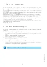
Perform the following operations and checks every 6 months according to intensity of use of the
automation.
Disconnect the 230 V~ power supply and batteries if present:
- Clean and lubricate, using neutral grease, the turning pins, the hinges of the gate and the drive
screw
- Check that fastening points are properly tightened.
-
Check the electrical wiring is in good condition.
Reconnect the 230 V~ power supply and batteries if present:
- Check the power adjustments.
- Check the good operation of all command and safety functions (photocells).
-
Check the good operation of the release.
-
If present, check for battery continuity by powering off and performing several manoeuvres in
sequence. Upon test completion, power back on (230 V~).
NOTE: For spare parts, see the spares price list.
8 . Routine maintenance plan
i

