32
IP2253EN - 2017-01-10
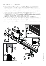
6.4 Installing the gearmotor
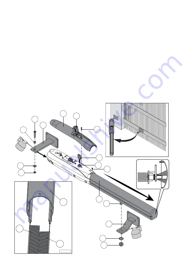
• Open the lock window [8], loosen the screw 6.3 x 19mm [9] and remove the rear cover [7].
Loosen the screw M4 x 8mm [10] and take out the front cover [11] as shown in the figure.
Release the piston by inserting the key [23] in the relative lock [24] and turning it clockwise (see
the USER INSTRUCTIONS).
• Fasten the piston to the rear bracket [17] using the screw M8 x 45mm [19], the bush [20] and the
washer Ø 24mm [21], then tighten the self-locking nut M8 [22] as far as it will go.
• Open the gate wing manually and insert the front coupling pin [25] in the hole of the front fas-
tening bracket [18]. Lock the pin in the bracket using the washer Ø30mm [26] and nut M16 [27]
supplied. Before installing the piston, grease the rotation points.
NB: pay special attention to the correct positioning of the washer on the brackets.
• Insert the protective brushes [12] in the relative guides on the front cover [11] and push them
well down (see Fig. 6.1). After making the adjustments (par. 6.5 and 6.6), insert the front cover
[11] on the drive screw and fix it in place using the screw [10].
NB: make sure the drive screw [25] enters the head of the cover [11] correctly (detail shown in
the figure below).
9
24
10
23
21
22
25
18
26
27
8
7
19
17
11
20
11
12
12
Fig. 6.1

