4
IP2058 - 2015-05-12
General safety precautions
This installation manual is intended for professionally competent personnel
only. Read the instructions carefully before beginning to install the product.
Incorrect installation may be a source of danger. Packaging materials (pla-
stic, polystyrene, etc.) must not be allowed to litter the environment and must be
kept out of the reach of children for whom they may be a source of danger. Before
beginning the installation check that the product is in perfect condition. These
instruction must be kept and forwarded to all possible future user of the system.
EC declaration of conformity
The manufacturer Entrematic Group AB, with headquarters in Lodjursgatan
10, SE-261 44 Landskrona, Sweden, declares that the safety device: SOF2M15-
SOF2M20-SOF2M25-SOF3M15-SOF3M20-SOF3M25 is compliant to the following
European directives and regulations: Machinery directive 98/37/CE; EN12978,
EN12453, EN12445;
EMC directive 2004/108/CE.
Landskrona, 2015-05-05
Marco Zini
(President & CEO
)
1. Technical data
Contact range
0,5 A - 24 V~ /
Temperature
-10° C - +50° C
Stroke from contact to intervention
max 15 mm
Stroke from intervention to mechanical stop
max 40 mm
Opening time of contacts after intervention
max 0,1 s
Recovery time from maximum deformation
max 0,5 s
Maximum applicable force
1 KN
Maximum speed of device
0,25 m/s
Dimensions SOF2M15-SOF3M15
30x1500x80 mm
Dimensions SOF2M20-SOF3M20
30x2000x80 mm
Dimensions SOF2M25-SOF3M25
30x2500x80 mm
Degree of protection
IP54
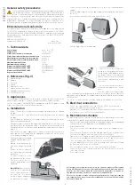
2. References (fig. 3)
[A] Aluminium profile
[B] Rubber
[C] Steel wire
[D] Spring
[E] Adjustment screw
[F] Edge activation limit switch
[G] Spring breakage limit switch
[H] Position limit switch
3. Applications
The safety edge SOF2M-SOF3M is a safety device to be used only in systems with
automatic doors and gates, to protect people from knocks and/or crushing.
Use the safety edges SOF2M-SOF3M in combination with DITEC products, and
respect the instructions enclosed with each product.
4. Installation
-
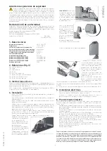
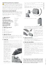
(Fig. 4.1) Loosen the screw that fastens the upper lid, and remove the lid from
the edge.
-
(Fig. 4.2) Loosen the screws that fasten the lower lid, and remove the lid from
the edge.
-
(Fig. 4.3) Mark the position [S] of the upper side of the fastening slot on the
side of the aluminium profile.
- Arrange the edge in its final working position, and mark the reference position
(noted earlier) on the destination surface. During the vertical assembly, keep
a minimum distance of 30 mm from the ground, directing the device as shown
in fig. 4.2.
- (Fig. 4.4) Drill the edge support surface about 7 mm beneath the reference
point, and fasten the spring with the appropriate elements (screw for metal,
screw and anchor plug for walls).
- Position the edge on the spring,
and pull it downwards to con
-
nect it.
- Mark the fastening holes on the
wall, in line with points [C] and
[D].
- Remove the device and drill
the fastening holes marked
previously.
- Reconnect the device to the
spring and fasten the screws.
- Check the screw of the steel
wire blocking terminal is well
tightened.
-
(Only SOF3M)
Check the rol-
ler on the lever is positioned
on the central limit switch. If
this is not the case, loosen
the blocking nut and adjust
the position of the castor.
-
Connect a tester to the two terminals to check there is a continuous power
supply.
- Press the rubber edge to check the power supply is interrupted, then disconnect
the tester.
- Insert the lower lid in the notch, and fix it with the screws.
-
Drill the upper lid in the marked part.
- Insert the electric wires, to be con-
nected to the control panel; fix them to
the lid using a cable gland to ensure
the degree of protection indicated
(IP54). Connect them to the terminals
then insert the lid and fasten it with
the screw.
- Check the intervention of the device
when functioning with the control
panel.
Note: the cables connecting the edge
to the control panel must be positioned in ducts or casings so they are protected
against mechanical damage. The equipment must be powered with a secure voltage
(SELV or PELV).
The electric circuit at the source must be limited to a maximum current of 0.5 A.
5. Electrical connections
- Connect the edges SOF2M to the card SOFA1 or SOFA2, as shown in fig. 1.
- Connect the edges SOF3M as shown in fig. 2.
Warning: if the control panel does not contain terminal 41, connect the edge
to terminals 1-8 or 1-6 or 1-7 of the control panel.
6. Maintenance schedule
The regular maintenance must be carried out every 12 months by personnel with
installation skills, and the following instructions must be observed.
- Check the lids (upper and lower) and the aluminium support are not damaged
or deformed; check the rubber part is not damaged or torn.
- Disassemble the lid.
- Check the steel wire is not damaged or frayed; replace the equipment if ne-
cessary.
- Loosen the wire [C] and check that the spring [D] provokes the activation of the
limit switch [G] (and the limit switch [H] in the case of SOF3M).
- Tighten the wire [C] again, using the adjustment screw [E], and position the
lever exactly in the middle between the limit switches [F] and [G] (check the
correct activation of the limit switch [H] in the case of SOF3M).
- Press the rubber [B] to check the correct activation of the limit switch [F] (and
the limit switch [H] in the case of SOF3M).
- Check the tightness of the electric connections with the terminals.
- Connect a tester to the terminals and press the limit switches to check for
correct functioning.
- Reassemble the lid.
All the rights concerning this material are the exclusive property of Entrematic
Group AB. Although the contents of this publication have been drawn up with the
greatest care, Entrematic Group AB cannot be held responsible in any way for
any damage caused by mistakes or omissions in this publication.
We reserve the right to make changes without prior notice. Copying, scanning
and changing in any way are expressly forbidden unless authorised in writing by
Entrematic Group AB.
ENGLISH


