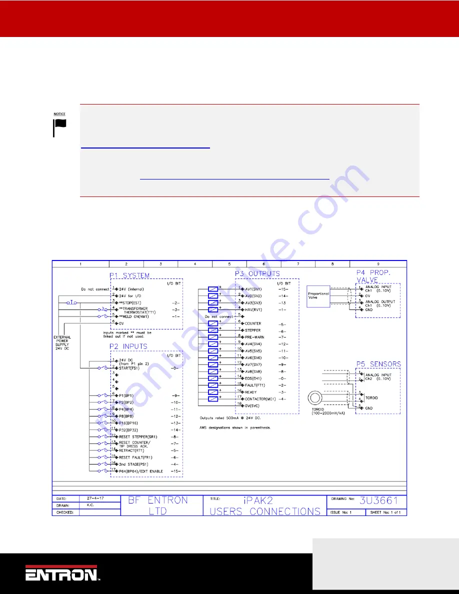
ADDITIONAL WIRING DIAGRAMS
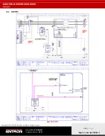
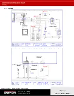
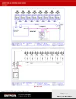
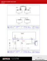
Customer Connections Diagram (3U3661)
222 |
P a g e
Copyright © 2021 BF ENTRON and/or its affiliates. All rights reserved
Product Model:
iPAK2v2
Firmware Version:
V2.10
May 22 | Doc No 700253-2
12
ADDITIONAL WIRING DIAGRAMS
The additional wiring diagrams for standard products are found in this section. The complete list of part numbers and
corresponding wiring diagrams can be found in
Table 6: Standard Product Wiring Diagram List by Part Number
DOCUMENTATION REQUEST
If your part number is not defined in
, please email ENTRON at
customerservice@entroncontrols.com
to request the drawing for your product. Please include the
following in your request:
your name
,
company name
,
part number
, and
product serial number
.
You can also visit
www.entroncontrols.com/resources/entron-library.html
wiring diagrams.
12.1
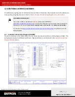
Customer Connections Diagram (3U3661)
The user connections on the iPAK2v2 Weld Timer for inputs and outputs are defined in Wiring Diagram 3U3661. This
wiring diagram applies to all iPAK2v2 weld timers. Diagram 3U3661 can also be found in the

