FAULTS & TROUBLESHOOTING
LED Indicators on Timer
119 |
P a g e
Copyright © 2021 BF ENTRON and/or its affiliates. All rights reserved
Product Model:
iPAK2v2
Firmware Version:
V2.10
May 22 | Doc No 700253-2
6.2.2
Ready LED
The Ready LED defines whether or not the control is ready for use.
LED Pulse
State
Flashing at 1 Hz
The control is ready for use
OFF
The control is not Ready. Check status messages
Table 40: Ready LED States
6.2.3
Sequence LED
The Sequence LED is ON when the control has accepted a START signal is actively running a weld program.
6.2.4
Weld LED
The Weld LED is ON when the control turns on the welding current.
6.2.5
Data Send/Receive LEDs
Lights numbered 5 through 12 corresponds signals for the COM ports numbered 2 through 5. The Send LEDs are defined
with odd numbers. The Receive LEDS are defined by even numbers. When communications are being sent or received,
the LED will flash.
6.2.6
Network Status / Module Status LEDs
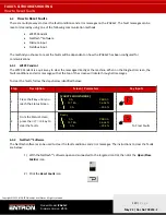
The Network Status (NS) and Module Status (MS) LEDs signify the status of the EtherNet/IP communications.
Upon power up the LEDs will perform the sequence in
LE1/MS
LE2/NS
Duration [s]
Green
Off
0.25
Red
Off
0.25
Off
Green
0.25
Off
Red
0.25
Table 41: NS/MS LED Power Up Sequence
After the power-up sequence is complete the LEDs indicate as follows:
LE1/MS
– EtherNet/IP
Status
Green
OK
Red
Fault
Table 42: MS EtherNet/IP Status LED
LE12/NS
– Network
Status
Green Flashing
Ready, no EtherNet/IP connection
Green Solid
EtherNet/IP class 1 connection
Red Flashing
EtherNet/IP class 1 connection lost
Table 43: NS Network Status LED


