background image

4

5

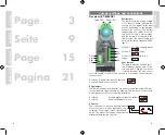
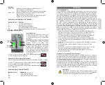
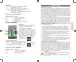
Indicators:

Green Led: 

Indicates power on the receiver (alignment mode disabled)


On, at optimal signal (alignment mode enabled)

Yellow Led: 

Indicates that the sensors can see each other 


(alignment mode disabled).


Indicates sensor alignment signal strength by blinking  


(alignment mode enabled).

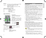
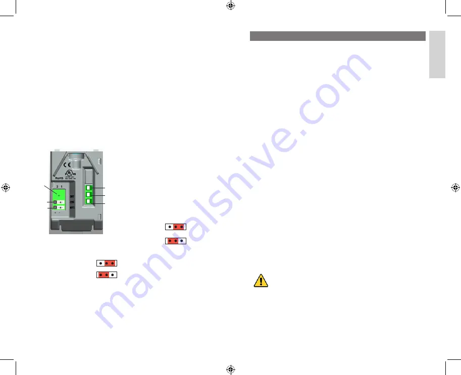
Connection to the receiver (ET-8060RX)

Wire connection:  Function:

V+ 


18-34VAC/DC Supply Class 2

V- 


18-34VAC/DC Supply Class 2

NO  


NO relay output


COM relay output

NC 


NC relay output. Safe mode

Green indicator:


This indicator shows that the sensor is 

supplied and emitting infrared light.

Sync jumper:

The jumper must be enabled (position 

2) when using two sets of sensors and 

an AC supply. To prevent crosstalk 

between the two sensor sets, the supply 

cords must be crossed to synchronize 

the emitter and receiver sets.

Position 1: Disable sync function    

 (default)

Position 2: Enable sync function

Mute jumper:

This jumper changes the function of the test/mute input.

Position 1: Test function active when mute input is connected to V+ 


 (default)

Position 2: Test function active when mute input is connected to V-

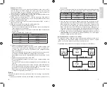
Connection to the emitter (ET-8060TX)

Wire connection: 

Function:

V+  

 18-34VAC/DC Supply Class 2

V-   

 18-34VAC/DC Supply Class 2

MU  

 Mute/Test input

Emitter (ET-8060TX)

V+
V-
MU

Sync

Mute

Green 

LED

Warning

Safety precautions

This manual contains important information regarding safety during instal-

lation, we highly recommend that you read the manual carefully before in-

stalling the sensor. Save the manual for future use.

Installation and use must be carried out with respect to the latest laws, 

provisions and rules in order to secure maximum safety.

According to the most recent European legislation, Industrial doors and 

gates are listed in the Machinery Directive 98/37/CE and more specifical-

ly the provisions under EN13241-1; EN12453; EN12978 standards. As for 

the North American market, the information is listed in the latest UL325 

standards.

The information in this manual is to be used by a qualified fitters and is not 

meant to be used by the end user of the door or gate.

The ET-8060 sensor must only be used as described in this manual. Im-

proper use may cause damage and personal injury.

•  Do not modify or change any components unless it is specified in the  

  manual. Changes to the sensor can cause malfunctions. Entrya 


  Technologies disclaims any liability for damages due to modification of  

  the sensors.

•  The sensor must only be used in through-beam installations and not in  

  a retro-reflective mode using a reflector.

•  The sensor must be mounted on a solid vibration-free surface.

•  The correct cable and conductor size is specified in the specifications.

•  Make sure that the power supply and load currents as well as other  

  parameters are within the specification of the sensor.

  For information concerning CE Declaration of Conformity, we refer to a  

  separate document.

Product description and applications

The ET-8060 through-beam photoelectric sensors are designed for pres-

ence detection (Type D according to EN12453) and can be used in indus-

trial doors and gates or similar applications that require detection of obsta-

cles interrupting the light beam from the emitter to the receiver. 

The lenses can be mechanically adjusted, and they are adjustable ±100° 

in the horizontal direction and ±30° in the vertical direction for correct op-

tical alignment between emitter and receiver – even on uneven surfaces. 

(See fig. A and B). The sensor is encapsulated in a vandal-proof aluminium 

cover.

Installation

The control system must be disconnected from the main pow-

er supply during installation. If backup batteries are present, 

these must also be disconnected.

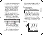
Check the following points before proceeding with the installation.

1. Check that the power supply is in accordance with the sensor specifi-

cation.

2. For distances between 0,6m…6m, 6m…12m or 12m…60m, see the 

distance jumper settings in “Jumper settings and connections”.

3. The emitter sends out light in an angle less than ±5° (according to 

ENGLISH

Summary of Contents for ET-8060

Page 1: ...ET 8060 Photoelectric sensor Photoelektrischer Sensor Capteur photoélectrique Fotocellen User Manual Bedienungsanleitung Manuel de l utilisateur Gebruikershandleiding ...

Page 2: ... prevent crosstalk between the two sensor sets the supply cords must be crossed to synchronize the emitter and receiver sets Position 1 Disable sync function default Position 2 Enable sync function Align jumper The jumper enables the alignment out connector and the yellow LED indi cates alignment signal strength by blinking This jumper is used for help with alignment of the sensors during installa...

Page 3: ... listed in the latest UL325 standards The information in this manual is to be used by a qualified fitters and is not meant to be used by the end user of the door or gate The ET 8060 sensor must only be used as described in this manual Im proper use may cause damage and personal injury Do not modify or change any components unless it is specified in the manual Changes to the sensor can cause malfun...

Page 4: ...ed for aligning the sensors at distances up to 6 m Adjust the emitter and receiver lenses until the yellow LED flashes until it flashes with the highest speed or lights up steadily If the green LED is lit the excess gain is higher than 4 After alignment move the alignment jumper back to position 1 see Jumper settings and connections Testing The sensors must be tested to verify that they are workin...

Page 5: ...tion 2 Reichweite 6 12 m Position 3 Steckbrücke entfernt Reichweite 0 6 6 m Steckbrücke Sync Die Steckbrücke muss aktiviert wer den Position 2 wenn zwei Gruppen von Sensoren und eine Wechselstromversorgung eingesetzt werden Um Übersprechen zwischen den beiden Sensorgruppen zu vermeiden müs sen die Versorgungsleitungen gekreuzt werden damit die Emitter und Empfängergruppen synchronisiert werden kön...

Page 6: ... Maschinenrichtlinie 98 37 EG aufgeführt genauer in folgenden Richtlinien EN13241 1 EN12453 EN12978 Für den nordamerikanischen Markt sind die Informationen den neuesten UL325 Normen zu entnehmen Die Informationen in diesem Hand buch sind für die Nutzung durch qualifizierte Installateure vorgesehen Sie sind nicht für den Endanwender der Tür bzw des Tors vorgesehen Der ET 8060 Sensor darf ausschließ...

Page 7: ...ander aus und fahren Sie mit der Ausrichtung fort bis die maximale Ausgangsspannung erreicht ist Setzen Sie nach der Ausrichtung die Steckbrücke für die Ausrichtung wieder in Position 1 siehe Abb I c Ausrichtung mithilfe der blinkenden gelben LED Setzen Sie die Steckbrücke für die Ausrichtung in Position 2 siehe Abb I Die gelbe LED kann zur Ausrichtung der Sensoren bis zu einer Entfernung von 6 m ...

Page 8: ...on plus courte et si le cavalier est incorrectement posi tionné l angle optique ne peut sat isfaire la norme de sécurité ESPE type 2 Position 1 distance 12 60 m par défaut Position 2 distance 6 12 m Position 3 cavalier déposé distance 0 6 6 m Cavalier sync sync jumper Cavalier sync sync jumper sur un système à deux jeux de capteurs alimenté en CA le cavalier doit être activé en position 2 Pour évi...

Page 9: ...ricain les informations sont listées dans les normes UL325 les plus récentes Les informations contenues dans ce manuel doivent être utilisées par des installateurs qualifiés Les informations contenues dans ce manuel doivent être utilisées par des installateurs qualifiés Leur usage n est en aucun cas destiné à l utilisateur final de la porte ou du portail Le capteur ET 8060 doit être utilisé seulem...

Page 10: ... de l autre et continue jusqu à obtention de la tension de sortie maximale Après alignement remettre le cavalier d alignement en position 1 voir Figure I c Alignement via la la LED clignotante jaune Mettre le cavalier d alignement en position 2 voir Figure I La LED jaune peut être utilisée pour aligner les capteurs jusqu à des distances de 6 m Ajuster les lentilles de l émetteur et du récepteur ju...

Page 11: ...andaard Positie 1 bereik 12 60 m standaard Positie 2 bereik 6 12 m Positie 3 verwijderd bereik 0 6 6 m Sync jumper Deze jumper moet ingesteld worden wanneer 2 sets fotocellen worden aangesloten met een AC voeding Om overspraak tussen de fotocellen te vermijden moeten de voedingskabels gekruist worden om de zenders en ontvangers te synchroniseren Positie 1 Sync functie uitgeschakeld standaard Posit...

Page 12: ...53 EN12978 standaarden De informatie in deze handleiding is bestemd voor gekwalificeerde installateurs en niet voor eindgebruikers van de poort of het hekwerk De fotocellen mo gen enkel gebruikt worden volgens hun beschrijving Onjuist gebruik kan leiden tot schade en lichamelijke letsels Wijzig of verander geen componenten tenzij het wordt vermeld in de handleiding Wijzigingen aan de fotocellen ku...

Page 13: ...lijning m b v de knipperende gele LED Plaats de jumper voor het uitlijnen op positie 2 De gele LED kan gebruikt worden voor het uitlijnen van fotocellen tot op een afstand van 6 meter Stel de lenzen van zender en ontvanger bij totdat de gele LED zeer snel knippert of continu oplicht Indien de groene LED oplicht is de signaalsterkte hoger dan 4 Plaats de jumper terug op positie 1 na het uitlijnen T...

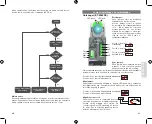
Page 14: ...maanden te controleren a h v de testprocedure en de lenzen te reinigen START IS RELAIS GEACTIVEERD IS RELAIS GEACTIVEERD IS RELAIS GEDEACTIVEERD ACTIVEER TEST DEACTIVEER TEST NORMALE FUNCTIONALITEIT GEEN BEWEGING TOEGESTAAN NEEN NEEN NEEN JA JA JA ABNORMALE FUNCTIONALITEIT Lens adjustment Linseneinstellung Réglage de lentille Bijstellen van de lenzen Manual adjustment Manuelle Einstellung Réglage ...

Page 15: ...le Einstellung Réglage horizontal Horizontaal bijstellen 100º Vertical adjustment Vertikale Einstellung Réglage vertical Verticaal bijstellen 30º B Wiring Diagram Schaltbild Schéma de câblage Bekabelingsschema Emitter Receiver Door control Mute input 18 34 V AC DC V V Mute V V NO C NC C Dimensions mm Abmessungen Dimensions Afmetingen 45 3 122 4 36 6 50 6 150 15 3 36 2 13 31 32 ENGLISH DEUTSCH FRAN...

Page 16: ... den Sensor von der Rückseite zu lösen Pour déposer le capteur de la partie arrière utiliser un tournevis Gebruik een schroevendraaier om de sensor los te maken van de behuizing Knock out for cable passage Knock out for cable passage Durchbruchteil für Kabel Durchbruchteil für Kabel Partie déconnectable pour le câble Partie déconnectable pour le câble Doorbreekdeel voor kabeldoorvoer Doorbreekdeel...

Page 17: ...put 18 34 VAC Emitter A Receiver A V V Mute V V Mute V V NO C NC V V NO C NC Crosstalk Übersprechen Interférence Overspraak Emitter A Emitter B Receiver A Receiver B Emitter A Receiver B Receiver A Emitter B G Emitter Emitter Sender Sender Émetteur Émetteur Zender Zender Receiver Receiver Empfänger Empfänger Récepteur Récepteur Ontvanger Ontvanger ENGLISH DEUTSCH FRANÇAIS NEDERLANDS ...

Page 18: ...frequenz Fréquence de marche Schakelfrequentie 10 imp sec Impulse s impulsions seconde impulsen seconde Specifications Technische Daten Caractéristiques Techniques Technische eigenschappen Response time Ansprechzeit Temps de réponse Responstijd OFF ON tON tON ON OFF tON Allumé Éteint tON ON OFF ON OFF tOFF tOFF OFF ON tOFF Éteint Allumé tOFF OFF ON 8 ms OFF Hold time AUS Haltezeit Temps de maintie...

Page 19: ...ocel gemonteerd op een mobiele steun Houd de voedingskabels van de fotocellen gescheiden van andere kabels bv motor om storing te vermijden van een inductieve spanning of stroompieken Trek niet aan de kabel Fotocellen mogen niet gebruikt worden als mechanische stop Repetitief buigen van de kabel moet vermeden worden NEDERLANDS ENGLISH DEUTSCH FRANÇAIS Incorrect 100 mm Correct e voltage ity switch ...

Page 20: ...38 39 Notes Notes ...

Page 21: ...Entrya Technologies www entrya com 15 029 796_MAN ET 8060 ENTRYA rev 10 06 2020 ...

Reviews: