6
7
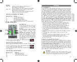
EN60496-2 ESPE2).
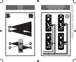
If an additional sensor set is mounted, interference may occur. In this
case, for sensors with AC supply, two sensor sets can be connected
in synchronization mode to eliminate crosstalk. See fig. G as well as
“Sync Jumper” in “Jumper settings and connections”.
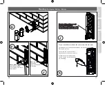
4. In case the back cable entrance is used, the PG cable gland must be
replaced by the blind cap. See fig. F and J.
5. Fix the sensor as shown in fig. E. To ease the mounting of the wires in
the terminal block, the sensor block can be separated from the base
using a screwdriver. See fig. K.
6. Connect the sensor to the door controller as shown in fig. C, in case a
single sensor is used.
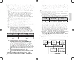
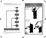
7. Align the lenses while following the guideline below:
a. Alignment using the laser alignment tool:
Switch on the laser and place it in the emitter’s lens holder. Align the
laser towards the receiver lens.
Place the laser in the receiver’s lens holder and align it towards the
emitter lens.
Alignment within ±0,5° is sufficient.
Distance between sensors
Alignment within diameter
6 m
Ø 0,1 m
12 m
Ø 0,2 m
30 m
Ø 0,5 m
60 m
Ø 1,0 m
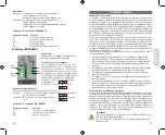
b. Alignment using the alignment output:
Move the alignment jumper to position 2 (see “Jumper settings and
connections”) and place the alignment test cable in “Align put”.
Connect also the test cable to a voltmeter (see “Jumper settings
and connections”).
Align the emitter and receiver lenses towards each other and contin-
ue doing so until the maximum voltage output is reached.
After alignment, move the alignment jumper back to position 1 (see
fig I).
c. Alignment using the flashing yellow LED:
Move the alignment jumper to position 2 (see “Jumper settings and
connections”).
The yellow LED can be used for aligning the sensors at distances up
to 6 m.
Adjust the emitter and receiver lenses until the yellow LED flashes
until it flashes with the highest speed or lights up steadily. If the
green LED is lit, the excess gain is higher than 4.
After alignment, move the alignment jumper back to position 1 (see
“Jumper settings and connections”).
Testing
The sensors must be tested to verify that they are working correctly after
installation.
1. Make sure that the sensors are installed according to instructions in
this manual.
2. Connect the power supply to both emitter and receiver and make sure
that no obstacles are present between them. The yellow LED is ON
(see “Jumper settings and connections”).
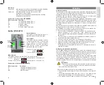
Yellow LED
Description
Action
On
Aligned
No Action required
Off
Not aligned
Remove obstacle
3. Once the sensors have been aligned and there are no obstacles in the
light beam, the sensor function can be tested by passing a 50-mm cyl-
inder through the light beam. First close to the emitter, secondly close
to the receiver, and finally in the centre between emitter and receiver.
Make sure that the yellow LED turns off and the relay output goes to
safe mode when the cylinder passes through the light beam. When the
cylinder is removed from the light beam, the LED goes back to normal.
4. Test that the sensors are performing correctly using the test body
700x300x200 mm according to EN12445 (EN12445 is to be merged
with the coming revision of EN12453).
Verification check of the door controller
To verify that cables, response times, relay outputs and sensors are work-
ing properly, we recommend testing the sensor before the door or gate
opens or closes by means of the sensor’s mute function.
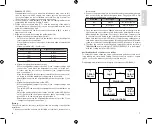
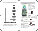
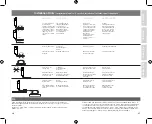
Designated architectures for a category-2 safety sensor EN13849-1
”TE”
Test
equipment
Door controller
Monitoring
i
m
i
m
”O”
Output
device
”OTE”
Output
of “TE”
”I”
ET-8060..
Sensor
”L”
Logic
ENGLISH

