background image

3 Packing and Feature 

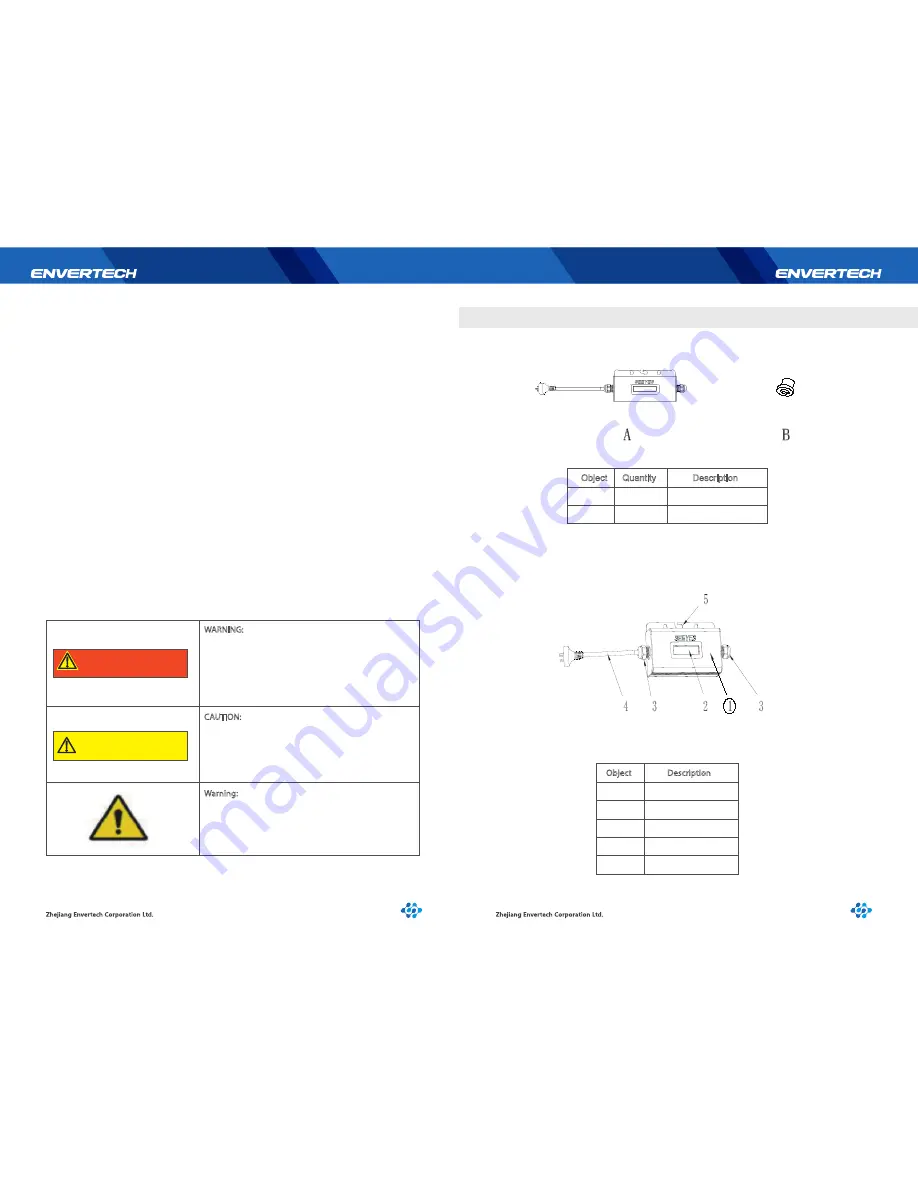
3.1 Assembly parts

3.2 Structure of EnverBridge

Object

Quantity

Description

A

1

1

B

  the EnverBridge safe running. 

5

6

!

WARNING

WARNING: Be aware that the input AC voltage 
of the Envertech EnverBridge shall not exceed 
the rated voltage; higher voltage may cause 
permanent damage to the device. It contains no 
user serviceable and Envertech-EnverBridge 
Warranty parts.

CAUTION: SAVE THESE INSTRUCTIONS– This 
manual contains important instructions for 
EnverBridge that shall be followed during 
installation and maintenance.

!

CAUTION

• Connection of any photovoltaic system to the electrical utility grid should only commence after 

   receiving prior approval from the utility company. 

• The EnverBridge MUST be installed and debugged complying with this manual by the professional 

  authorized by Envertech. 

• All electrical installation MUST meet the local standard. 
• To assure the safe running, must comply with the relative standard for using the tool properly and 
  Personal Protective Equipment (PPE). Away from the chemical and reagent. 
• The EnverBridge must installed environments suitable for it’s IP rating.
• CAUTION! The device is intended for fixed installation, Located on a part that is not removable 

   without impairing the operation of the unit. 

• CAUTION! Visible and legible to the operator during the normal operation of the device. 
• WARNINGS - Risk of electric shock- Do not open cover. No user serviceable parts inside. Servicing 

  limited to qualified service personnel. 

• WARNINGS - The printed circuit boards contain components sensitive to electrostatic discharge. 

   Wear a grounding wrist band when handling the boards. Do not touch the boards unnecessarily. 

• WARNINGS - Do not operate any device which is damaged, lacking parts or dented. Failure to 

   observe this warning may result in an electric shock, injury, fire or accident. 

• WARNINGS - Before installing the unit, agree with the customer the site. 
• WARNINGS - The output connection with AC grid shall be protected by a max. 20A circuit breaker. 
• The EnverBridge shall be connected with the Envertech EVT248 or EVT500 inverter as a system. It 

  cannot operate as a stand-alone unit or in case of AC grid disruption 

Warning:
Only authorized persons can be allowed for installation 
of inverter 

EnverBridge

Screw

Object

Description

1

2

3

4

5

Cover

LCD Screen

Cable gland

AC Cable

Frame

Summary of Contents for EnverBridge

Page 1: ...er Operating Manual Model Number EnverBridge This manual is an integral part of the unit Please read the instruction manual carefully before installation operation or maintenance Keep this instruction...

Page 2: ...id Connection 5 3 Grid Disconnect 5 4 Installation checklist 5 5 Start Up Checks 6 LCD Abstracts 6 1 Brief introduction 6 1 1 Function of LCD 6 2 LCD 1602 interface 6 2 1 Start up interface 6 3 Monito...

Page 3: ...ruction DANGER The DANGER symbols in this manual and on the EnverBridge Indicate a hazard with a high level of risk which if not avoided will result in death or serious injury CAUTION The CAUTION symb...

Page 4: ...not respond for any quality assurance and other risks For Envertech EnverBridge Warranty Terms and Conditions see the appendix of this manual 3 4 PV PCS _ Caution risk of electric shock CE mark is at...

Page 5: ...t installed environments suitable for it s IP rating CAUTION The device is intended for fixed installation Located on a part that is not removable without impairing the operation of the unit CAUTION V...

Page 6: ...07mm 3W 700g Natural convection no fans 40 65 IP65 CE 5 Years 7 8 Use the Power Line Carrier Communication PLCC technology within Photovoltaic power plant By PLCC technology EnverBridge collects gener...

Page 7: ...inverter array is exported to the utility grid Fault If the system does not operate correctly Envertech EnverBridge will stop automatically and enter into Disable mode The Envertech EnverBridge syste...

Page 8: ...these tests The data should be recorded in an equipment log If the device is not operating properly or fails any test the device has to be repaired 1 Inspect the equipment and accessories for mechanic...

Page 9: ...168 0 201 indicates a normal network connection and 192 160 0 254 indicates an abnormal network connection The figure of power efficiency which shows at the beginning of the second line indicates the...

Page 10: ...e the EnverBridge from the system Only trained and authorized professional personnel WHO ARE FAMILIAR WITH THE REQUIREMENTS OF SAFETY is allowed to perform servicing and maintenance work 6 5 Applicati...

Page 11: ...nverBridge Wear gloves and safety glasses Disconnect the EnverBridge from the Grid Isolating device Clean the EnverBridge with wet cloth carefully Introduction Use the monitoring website EnverPortal d...

Page 12: ...ill the EnverBridge serial Number in the blank space for example 90000001 click OK and finish the registration 19 20 9 Contact Zhejiang Envertech Corporation Ltd Tel 86 579 8926 6326 Email info envert...

Reviews: