background image

4.  With  the  “

F

igure

  5:  F

an


housing


overall


dimensions

.”

 and

 “F

igure

 6: m

inimum

 i

nstallation


C

learanCes


For

 F

an

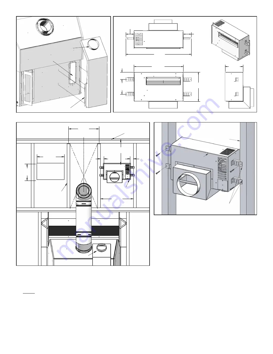
.” Cut a opening for the fan 

in the wall board; 

minimum 14⅜” by 8⅜”. It 

cannot be less than 12” from the ceiling and 

1¾” between fan housing to the closest stud 

or  combustible  materials.  Do  not  install  in 

front of the vent.

2x4 Wall Stud

Fan Housing

Fan Mounting Brackets

CL

Ceiling

2"x4" Wall Stud

Fan Housing

Fan

 Cu

t O

ut

12"

(305mm)

1

3

/

4

"

(44mm)

1

3

/

4

"

(44mm)

17

1

/

4

"

(438mm)

Min 14

3

/

8

"

(365mm)

Min 8

3

/

4

"

(222mm)

Hot Air Duct

TYP 16"

(406mm)

13

3

/

4

"

(349mm)

2"

4

1

/

16

"

(103mm)

8

1

/

16

"

(105mm)

2

1

/

4

"

(57mm)

2

1

/

4

"

(57mm)

18

1

/

4

"

(464mm)

5

1

/

16

"

(129mm)

Figure 4: Install the vent duct kit.

Rear of the Unit

Hot Air Duct

Opening

Fireplace

Vent Duct

Vent Duct Collar

Fireplace

Figure 5: Fan housing overall dimensions.

Figure 6: Minimum Installation Clearances for Fan.

5.  Mount and secure the fan housing assembly to the framing members or to the 2x4 wall studs using the 

mounting brackets and screws provided in the kit  (refer to Figure 7).

  Note:

  The brackets have a guided flange which provides the minimum spacing required between the fan 

housing and 2x4 wall studs or combustible materials.

6.  Wire the fan (refer to Figure 8)

a) Feed the 110-120 VAC electrical service wires through the strain relief and through the service hole on the 

bottom of the fan housing.

b) Secure the service wires to the strain relief.

c) Use the wire nut to join the wires to the service wire.

d) Secure the service ground wire to the ground screw on the cover plate.

Figure 7: Mounting fan housing.

Summary of Contents for 50-1935

Page 1: ... Front Access Cover 6 Fan 7 Fan Housing Assembly 8 Fan Housing Mounting Bracket 9 5 Round Flex Line Air Duct Figure 2 Remove the duct cover 1 Remove the rear standoff and the duct cover plate from the back of the unit Figure 3 Install the hot air ducts 2 Insert the hot air duct and the hot air duct angle into the cut out refer to Figure 3 Secure the ducts to the back of the fireplace through the p...

Page 2: ... Air Duct Opening Fireplace Vent Duct Vent Duct Collar Fireplace Figure 5 Fan housing overall dimensions Figure 6 Minimum Installation Clearances for Fan 5 Mount and secure the fan housing assembly to the framing members or to the 2x4 wall studs using the mounting brackets and screws provided in the kit refer to Figure 7 Note The brackets have a guided flange which provides the minimum spacing req...

Page 3: ...ons Figure 11 Install fan bezel grille Figure 10 Optional install with two 2 heat distribution kits Optional Note An 8ft 2 4m 5 Aluminum Flex Vent is provided Extra length of 5 Aluminum Flex Vent can be added using a coupling provided by the installer 9 Attach the fan bezel to the fan cut out and secure the fan bezel to the wall board with screws 10 Cover the cut out with a fan grille When install...

Page 4: ...February 18 2015 www enviro com C 14548 52 1 4 1327mm to Header A A 90 2286mm to Internal Ceiling 60 1524mm Chase Minimum Width 44 5 8 1133mm Minimum 26 1 2 610mm Chase Minimum Depth Minimum Height from the base of the unit Figure 12 Q4 Installation Clearances with Heat Distribution Kit ...

Reviews: