background image

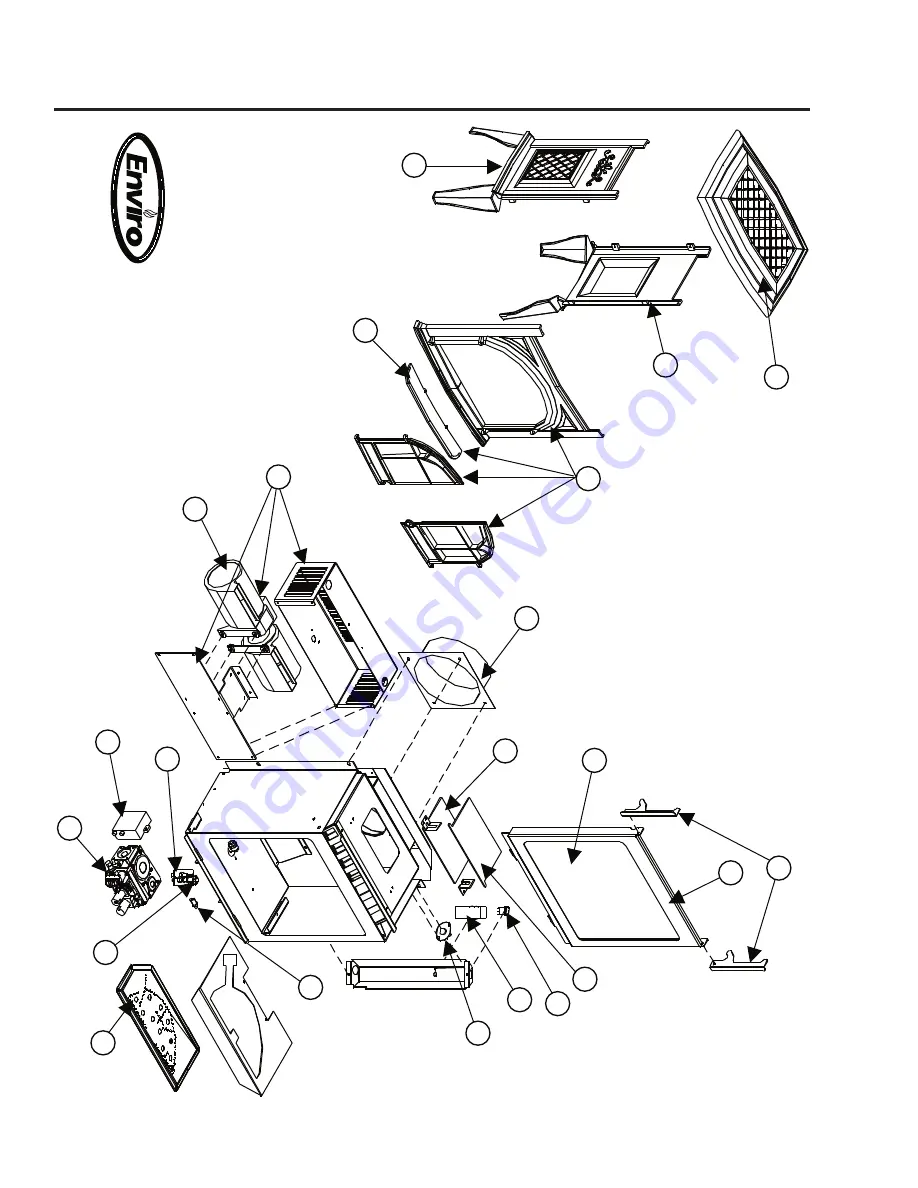
Parts Diagram

A

SC

O

T

-C

om

po

ne

nts

D

ec

em

be

r2

00

4

��

��

��

��

��

��

��

��

��

��

��

��

��

38

Summary of Contents for Ascot

Page 1: ...artment WARNING If the information in this manual is not followed exactly a fire or explosion may result causing property damage personal injury or loss of life Installation and service must be performed by a qualified installer service agency or the gas supplier FOR YOUR SAFETY Do not store or use gasoline or other flammable vapours and liquids in the vicinity of this or any other appliance Massa...

Page 2: ...s to the current CAN CGA B149 installation code Canada or National Fuel Gas Code ANSI Z223 1 2 USA To prevent injury do not allow anyone who is unfamiliar with the stove to operate it To prevent injury if the pilot or pilot and burners have gone out on their own open the glass door and wait 5 minutes to air out before attempting to re light the stove Always keep the area around these appliances cl...

Page 3: ...el Conversion 10 Initial Installation 12 Preparation For Installation 12 Clearances to Combustibles 12 Planning Your Installation 13 Vent Termination Restrictions 14 Fireplace Horizontal Vent Kit 50 1235 15 Other Approved Vent Parts 16 Vent Restrictor Setting 18 Horizontal Installation 19 Vertical Installation 22 Freestanding Drafthood Adaptor 50 841 25 Hearth Mount Installation 28 Gas Line Connec...

Page 4: ...VENTED GAS FIREPLACE HEATERS CAN CGA 2 17 M91 GAS FIRED APPLIANCES FOR HIGH ALTITUDES CSA P 4 1 02 TESTING METHOD FOR MEASURING ANNUAL FIREPLACE EFFICIENCY This ENVIRO ASCOT Fireplace Has been certified for use with either natural or propane gases See rating label Is not for use with solid fuels Codes And Approvals Is approved for bedroom or bed sitting room IN CANADA must be installed with a list...

Page 5: ...pth 15 5 8 inches 397 mm Center of flue to ground without leveling legs 18 3 8 inches 467 mm Center of flue to ground with leveling legs approx 19 inches 483 mm Figure 1 Dimensions of the Ascot RATING LABEL LOCATION The Rating Label is located on a plate hang on the back left of the unit ...

Page 6: ...e floor do not use any phone in your building the gas suppliers instr uctions If you cannot reach your gas supplier call the firedepartm ent Use only your hand to pushin or turn the gas control knob Call a qual ified service technician Force or Donot use thisappliance if any part has beenunder water C D Never use tools If the knob will not push in or turnby hand donot try to repair it attempted re...

Page 7: ...ed by turning the fan control knob To turn the blower off turn the knob COUNTER CLOCKWISE until it clicks off It is advisable not to operate the blower below 1 3 speed as it puts a strain on the windings of the blower and running the blower at lower speeds could also cause premature fan failure NORMAL SOUNDS DURING OPERATION Table 1 Normal Sounds Component Sound Reason Ascot Creaking when heating ...

Page 8: ... glass a temporary problem The glass will need cleaning initially after the first 4 hours of use and again about two 2 weeks after installation Use a mild glass cleaner and a soft cloth abrasive cleaners will damage the glass and enamel surfaces Depending on the amount of use the glass should require cleaning no more than two or three times a season Do not clean the glass when it is hot CLEANING T...

Page 9: ...e tape in a bottom corner Close door GLASS DOOR REMOVAL Maintenance And Service Figure 5 Removing inner glass door 9 Turn unit off and wait until the appliance has cooled down Remove the cast iron top from the unit by lifting straight up Lift the two door handles located on either side of the door and lift the glass door assembly straight up and out Carefully open the two doors and remove if neces...

Page 10: ...n or production of carbon monoxide may result causing property damage personal injury or loss of life The qualified service agency is responsible for the proper installation of this kit The installation is not proper or complete until the operation of the converted appliance is checked as specified in the manufacturer s instructions supplied with the kit Kit Parts List 1 Orifice NG 48 DMS or LP 57...

Page 11: ...crew is similar to what is shown in Figure 11 On some units you will need to pay special attention when installing the burner that the venturi adjustment rod is properly installed into the venturi adjustment piece welded to the burner venturi tube 9 Reconnect the main gas line if it was disconnected and open the shut off valve at the gas line to the unit 10 Use a small brush to apply a warm soapy ...

Page 12: ...e stove where it can be accessed by a gas supply line Locate the stove in a large and open room that is centrally located in the house This will optimize heat circulation and comfort As the stove can be equipped with a convection fan ensure that an electrical outlet is within 6 ft 1 8 m of the stove The flow of combustion and ventilation air must not be obstructed CLEARANCES TO COMBUSTIBLES A Side...

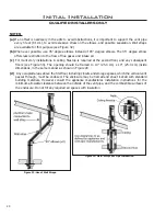
Page 13: ...lications a fire stop is required at each floor level If an offset is needed in the attic additional pipe and elbows will be required To connect the venting system to the appliance flue outlet a twist lock adapter is built into the appliance at the factory Refer to INITIAL INSTALLATION VENT CONFIGURATION AND RESTRICTOR SETTINGS for venting parameters Your total vent pipe length must be within the ...

Page 14: ...C 12 in 30 cm Clearance from permanently closed window to prevent condensation D 24 in 60 cm Vertical clearance to ventilated soffit located above the terminal within a horizontal distance of 2 ft 60 cm from center line of terminal E 18 in 45 cm Clearance to unventilated soffit F 12 in 30 cm Clearance to outside corner G 12 in 30 cm Clearance to inside corner H 3 ft 91 cm within a height of 15 ft ...

Page 15: ... 5 190 cm length of Ø4 10 cm double walled flex pipe 12 9 16 tech screws 1 5 190 cm length of Ø65 8 16 8 cm double walled flex pipe 8 11 2 wood screws Please ensure that all components are supplied with this kit If components are missing or have been damaged contact your dealer distributor or courier company Do not attempt the installation if components are missing or damaged INSTALLATION INSTRUCT...

Page 16: ...rminal slide the Ø65 8 16 25 cm flex intake liner over the collar secure the flex liner with three 3 sheet metal screws evenly spaced 14 Attach the vent terminal to the outside of the house using four 4 wood screws provided 15 Light the appliance and ensure proper operation OTHER APPROVED VENT PARTS Table 3 Approved Vent Manufacturers Manufacturer Trade Name Nominal Sizes American Metal Products A...

Page 17: ... elbow black 950 4DT VS SV4VS Vinyl siding standoff sheild 942 4DT WT SV4RSN 4DWT Wall thimble 953 4DT SC SV4FC 4DSC Storm collar 963 4DT FS SV4BF 4DFSP Fire stop 988 4DT WS B SV4BM 4DWS Wall strap support band 970 4DT HKA SV0SHK 4DHTK1 Horizontal termination kit SD Basic Kit SEL Kit A SC Standard Kit 911 11 to 14 5 8 pipe adjustable 4DT AJ 4D12A 4 to 10 pipe adjustable SV4LA12 11 2 to 12 pipe adj...

Page 18: ...fer to Figure 20 to determine were the vent restrictor should be set for proper operation The numbers in the chart represent the actual vent restrictor settings Although the numbers do not appear on the unit use this guide to follow Ensure that the setscrew is retightened and the unit is checked for proper operation Figure 20 Possible Vent Configurations Figure 19 Vent Restrictor Settings Wait for...

Page 19: ...ion 19 Place a bead of Mil Pac on the outer edge of the inner exhaust pipe non flared end Place a bead of high temperature silicone on the male edge of the outer pipe Push the pipe sections completely together then twist lock one section clockwise approximately 1 4 turn until the two sections are fully locked The female locking lugs will not be visible from the outside on black pipe They may be lo...

Page 20: ...pace will exist between the wall and the vent termination Initial Installation QUALIFIED INSTALLERS ONLY Wood screws x4 Cut vinyl siding away to fit standoff Bolt x4 required Nut x4 required Wood screw x4 Figure 24 Installing Vent Cap with Vinyl Siding Stand Off Figure 25 Installing Horizontal Vent Termination STEP 3 With the pipe attached to the stove in the correct location mark the wall for a 1...

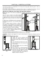
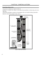
Page 21: ...ownward This could cause high temperature and may present the possibility of a fire 2 The location of the horizontal vent termination on the exterior wall must not be easily blocked or obstructed Refer to INITIAL INSTALLATION VENT TERMINATION RESTRICTIONS 3 When installing a vent pipe in a chase the minimum clearance to combustibles is 2 51 mm NOTE Vent pipe must not be longer than 18 457 mm maxim...

Page 22: ...ot pack air spaces with insulation 2 Set the gas appliance in the desired location Drop a plumb bob down from the ceiling to the position of the appliance flue exit and mark the location where the vent will penetrate the ceiling Drill a small hole at this point Next drop a plumb bob from the roof to the hole previously drilled in the ceiling mark the spot where the vent will penetrate the roof Det...

Page 23: ...he height of the vent cap meets the minimum code requirements Refer to Figure 31 and Table 5 Note that for steep roof pitches the vent height must be increased In high wind conditions nearby trees adjoining roof lines steep pitched roofs and other similar factors can result in poor draft or down drafting In these cases increasing the vent height may solve the problem Figure 30 Vertical Vent Termin...

Page 24: ...less restriction to the flow of flue gases and intake air c For multi story installations A ceiling firestop is required at the second floor and any subsequent floors see Figure 33 The opening should be framed to 10 25 4 cm x 10 25 4 cm inside dimensions in the same manner as shown in Figure 28 d Any occupied areas above the first floor including closets and storage spaces which the vertical vent ...

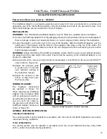
Page 25: ... the collar and or flue outlet Ensure that the opening of the Drafthood Adaptor is not blocked or obstructed 3 Being careful not to run any wiring tight across metal edges connect them to the valve and ON OFF switch refer to Figure 39 Optional remote control receiver ON OFF Remote thermostat switch Purple Grey Blue Grey Grey Optional Thermostat Optional wall switch Valve Drafthood adaptor 300oF 14...

Page 26: ...system see Figure 40 41 In either case the fireplace may be connected to the chimney vent using a 4 10 cm single wall vent connector When an existing masonry chimney is utilized for the venting we recommend the vent connector be connected to an approved 4 10 cm diameter flue liner running the full height of the chimney In many jurisdictions this flue liner may be mandatory If 4 10 cm single wall v...

Page 27: ... Figure 39 3 Remove the four mounting screws holding the spill switch bracket and remove the bracket see Figure 43 4 Remove and replace the spill switch with a 50 885 Spill Switch Assembly using a T 20 torx type driver 5 Follow the reverse of the previous steps OPTIONAL FINISHING In installations where the flue connector is running from the drafthood into a non combustible chimney the following op...

Page 28: ...ng venting manufactures coaxial to co linear adapters at the unit and at the chimney termination Maximum vertical chimney height 15 feet 4 57 m 15 feet 4 57m Maximum Vertical Venting If installed on a carpeted surfacea hearth is required 2 3 51mm 76mm Collinear Pipes Existing Masonry Chimney Lock Damper in the Open Position Seal Plate Cap Assembly Coaxial to Collinear Adapter Figure 44 Hearth Moun...

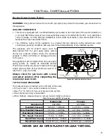
Page 29: ...must be isolated from the gas supply piping system by closing its individual manual shutoff valve during any pressure testing of the gas supply piping system at test pressures equal to or less than 1 2 psig 3 45 KPa Always check for gas leaks with a soap and water solution after completing the required pressure test TO TEST VALVE PRESSURES The pressure taps are located on the left side of the valv...

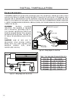
Page 30: ...s Control Valve Thermopile ON OFF Thermostat Grey Optional Thermostat Pilo Adjustment Screw Figure 47 Wiring Diagram For Fan Control Figure 46 Wiring Diagram For Gas Valve Table 7 Recommended Thermostat Wire Size Wire Size Max Length 14 gauge 100 ft 30 48 m 16 gauge 60 ft 18 29 m 18 gauge 40 ft 12 00 m 20 gauge 25 ft 7 62 m 22 gauge 18 ft 5 49 m WARNING Electrical grounding instructions This appli...

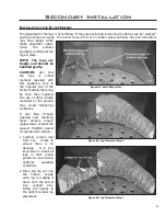
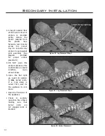
Page 31: ...ial supplied with this appliance Due to the irregular size of the ember material there may be more than required The use of other foreign materials on the burners may create dangerous conditions If over time through cleaning and servicing these embers require replacement contact the nearest ENVIRO dealer for replacement embers 1 Carefully remove logs from box Check to ensure there is no damage It ...

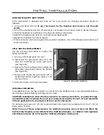
Page 32: ... pilot assembly See diagram provided for proper ember placement 4 DO NOT pack this ember material as this could create an unsafe condition leave embers loose 5 Upon the first light up watch for ignition to ALL burner ports If a long delay is noted First wait for the appliance to cool down Open the front door of the appliance Check to carefully reposition the embers making sure that burner ports ar...

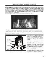
Page 33: ...peration Figure 55 Optional Fan Kit Installation CAUTION NEVER OPERATE THIS APPLIANCE WITH THE DOOR REMOVED Important note When the unit is turned on for the first time It should be turned onto high without the fan on for the first 4 hours This will cure the paint logs gasket material and the other products used in the manufacturing process It is advisable to open a window or door as the unit will...

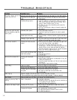
Page 34: ...rew check pilot head for damage Check thermocouple voltage at valve It must be greater than 5 mV If low replace thermocouple Air in gas line pilot dies while knob is depressed Bleed line Check gas line pressure Contact dealer Burners will not remain lit Problem with thermopile circuit Check gas line pressure Check for flame impingement on thermopile If low see Pilot will not remain lit Check therm...

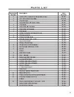
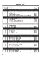
Page 35: ...C 044 Window Channel Tape EC 058 6 Simpson Dura Vent GS Adaptor EC 060 5 Fan Controller With Knob 115V EF 045 7 Fan Kit 30 056 Screen 30 057 8 Relief Door Gasket 50 019 9 Door Painted 50 020 10 Burner Assembly Complete 50 021 Log Set With Embers 50 022 Lighting Instructions French 50 023 Lighting Instructions English 50 024 Owner s Manual 50 029 1 Door Knob Silver 50 030 Valve Cover 50 089 Electro...

Page 36: ...ed Black 50 031 18 Top Antique White 50 032 18 Top Diamond Black 50 033 18 Top Inferno Red 50 034 18 Top Pearl Grey 50 035 18 Top Wedgewood Blue 50 036 18 Top Westport Green 50 037 18 Top Antique Chestnut 50 855 19 Side panel right Painted Black 50 052 19 Side panel right Antique White 50 053 19 Side panel right Diamond Black 50 054 19 Side panel right Inferno Red 50 055 19 Side panel right Pearl ...

Page 37: ...helf Inferno Red 50 076 22 Front complete with doors ash shelf Pearl Grey 50 077 22 Front complete with doors ash shelf Wedgewood Blue 50 078 22 Front complete with doors ash shelf Westport Green 50 079 22 Front complete with doors ash shelf Antique Chestnut 50 859 Complete cast body Painted Black 50 569 Complete cast body Antique White 50 570 Complete cast body Diamond Black 50 571 Complete cast ...

Page 38: ...Parts Diagram ASCOT Components December 2004 38 ...

Page 39: ...e 1 Year Warranty Under this warranty Sherwood Industries Ltd covers all exterior surface finishes against defects in materials and workmanship for part repair or replacement and limited labour for the first 1 year to the original purchaser Please see the exclusions and limitations section below as certain restrictions and exclusions apply to this warranty Here is how our Warranty works If you hav...

Page 40: ...e offsets negative air pressures or other influences caused by mechanical systems such as furnaces fans clothes dryers etc 12 The Limited Warranty is void if a The stove has been operated in atmospheres contaminated by chlorine fluorine or other damaging chemicals b The stove is subject to submersion in water or prolonged periods of dampness or condensation c Any damage to the unit combustion cham...

Page 41: ...le for travel costs for service work In the event of in home repair work the customer will pay any in home travel fees or service charges required by the Authorized Dealer 28 At no time will Sherwood Industries Ltd be liable for any consequential damages which exceed the purchase price of the unit Sherwood Industries Ltd has no obligation to enhance or modify any stove once manufactured example as...

Page 42: ...______________________________ MODEL ___________________________________ SERIAL NUMBER ___________________________ DATE OF PURCHASE _____________ dd mm yyyy DATE OF INSTALLATION ___________ dd mm yyyy NATURAL GAS NAT PROPANE LPG INLET GAS PRESSURE _________in wc MAIN BURNER ORIFICE __________ DMS PILOT ORIFICE _________OR________in diam INSTALLER S SIGNATURE _______________________________________...

Reviews: