38
Initial Installation
QUALIFIED INSTALLERS ONLY
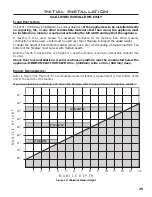
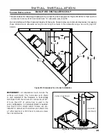
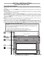
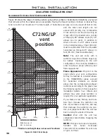
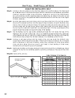
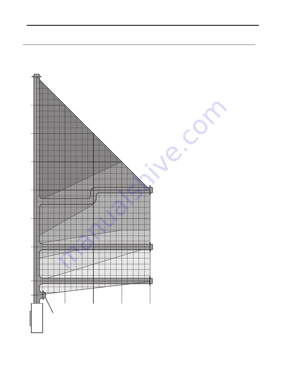
Figure 49: NG/LP Vent Graph
a
LLowabLe
c
o
-a
xiaL
V
ent
c
onFiguRations
:
Figure 49 shows the range of venting options using either vertical or horizontal terminations; any layout
that remains within the shaded area is acceptable. Having the fewest number of elbows is ideal as they
tend to restrict air movement. The total length of horizontal vent pipe can not exceed 20 feet (6.1m)
and the total vent length can not
exceed 40ft (12.2m). Any combination
of rise and run can be used as long as
it lays within the shaded area (a total
of three (3) 90˚ elbows or six (6) 45˚
elbows can be used). In addition to
what is shown, if a 90
˚
elbow is used
in the horizontal plane, 3 feet (91.4cm)
must be subtracted from the allowable
horizontal run (for each 45
˚
elbow, 1½
feet (45.7cm) must be subtracted).
Note: The unit will come with 6
restrictor rings. One of these rings may
be needed depending on the vent
configuration. This must be installed in
order to achieve proper efficiency and
flame appearence.
Flame Appearence:
Pin point on the
graph where your vent configuration
will lay. Remember to consider elbows
in the HORIZONTAL plane account
for horizontal distance as stated
above. Use the corresponding exhaust
restrictor accorinding to the graph. See
the following section in this manual for
installation details. Your climate and
altitude may alter what restrictor is
required for your particular application.
If your flame is low, flickery, and more
blue then increase the restrictor one
size. If your flame is tall, thin, and lazy
then decrease the restrictor one size.
Use your judgement after the unit has
been running for about 20 minutes.
Caution: Wait until the unit has
completely cooled before changing the
restrictor.
NOTE: If longer vent runs are required,
50-3884 C-G Series Horizontal
Powervent kit is available for vent runs
of up to 110 feet.
5’
(1.52m)
4’
(1.22m)
30”
(0.76m)
10’
(3.05m)
10’
(3.05m)
15’
(4.57m)
15’
(1.52m)
20’
(6.1m)
20’
(6.1m)
25’
(7.62m)
30’
(9.14m)
35’
(10.7m)
40’
(12.2m)
RESTRICTOR 1
RESTRICTOR 1
RESTRICTOR 1
RESTRICTOR 2
RESTRICTOR 2
RESTRICTOR 2
RESTRICTOR 3
RESTRICTOR 3
RESTRICTOR 3
RESTRICTOR 5
RESTRICTOR 5
RESTRICTOR 5
RESTRICTOR 4
RESTRICTOR 4
RESTRICTOR 4
NO RESTRICTOR
NO RESTRICTOR
NO RESTRICTOR
C72 NG/LP
vent
position
MINIMUM VENTING:
NG: Restrictor 1.5
LP : No Restrictor
**Vertical vent height does not account for elbows
Summary of Contents for C72I
Page 55: ...55 Parts Diagram 1 2 3 4 5 6 9 7 8 12 13 14 10 15 15 ...
Page 57: ...57 Notes ...
Page 58: ...58 Notes ...

