background image

50

Secondary Installation

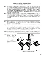
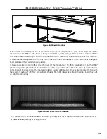
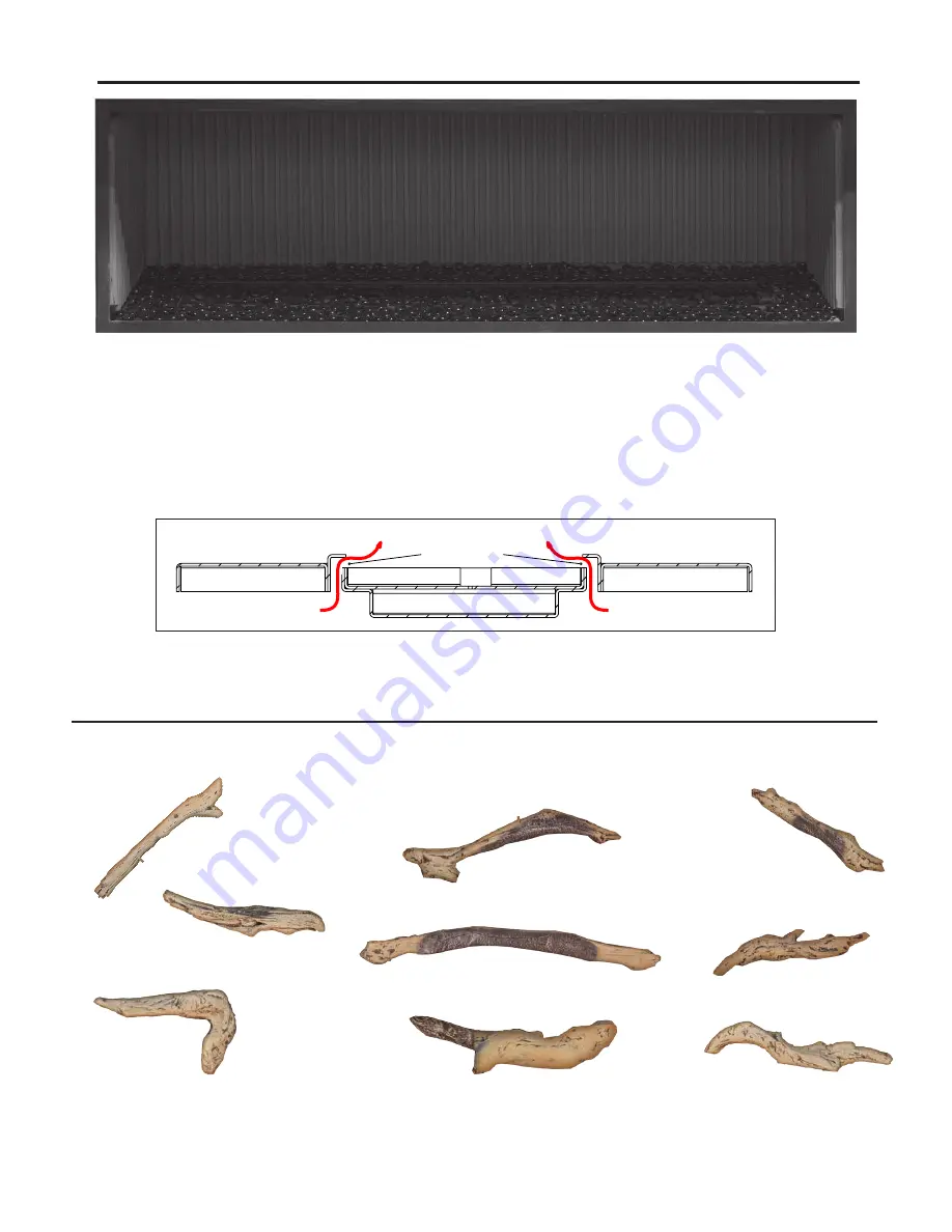
Figure 67: Glass Media Bed

9. You have now successfully installed your panels and media base. You may now arrange your 

optional 50-3691 (Driftwood Log Set); see instruction sheets for further detail.

10. Re-install the glass door and safety screen.

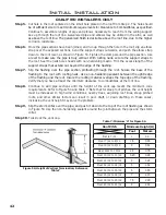
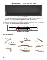
IMPORTANT: IF THE AIR SLOT AROUND THE BURNER IS BLOCKED WITH MEDIA THIS 

WILL CAUSE THE FIREPLACE NOT TO BURN PROPERLY.

AIR

AIR

AIR SLOT

Figure 68: Burner Side Cross Section

LOG #6

LOG #5

LOG #4

LOG #2

LOG #1

LOG #3

LOG #8

LOG #7

LOG #9

L

og

 s

et

 i

nstaLLation

:

Summary of Contents for C72I

Page 1: ...ury or loss of life Installation and service must be performed by a qualified installer service agency or the gas supplier Version Française www enviro com fr html C 4001609 W A R R A N T Y R E G I S T R A T I O N e n v i r o c o m w a r r a n t y C72I C72ID D I R E C T V E N T F I R E P L A C E I P I CERTIFIED TO CERTIFIÉ AUX ANSI Z21 88 CSA2 33 CSA 2 17 ...

Page 2: ... immediately Immediately call your gas supplier from a neighbor s phone Follow the gas supplier s instructions If you cannot reach your gas supplier call the fire department Installation and service must be performed by a qualified installer service agency or the gas supplier Massachusetts installations Warning This product must be installed by a licensed plumber or gas fitter when installed withi...

Page 3: ...be performed by a qualified installer service agency or gas supplier This installation must conform to local codes or in the absence of local codes with the National Fuel Gas Code ANSI Z223 1 NFPA 54 or the Natural Gas and Propane Installation Code CSA B149 1 To prevent injury do not allow anyone who is unfamiliar with the stove to operate it To prevent injury if the pilot or pilot and burners hav...

Page 4: ...ous Pilot Mode 12 Maintenance And Service 15 Routine Maintenance 15 Cleaning The Glass 15 Cleaning The Firebox 15 Replacing the Glass 15 Cleaning Decorative Surfaces 16 Safety Screen 16 Maintenance And Service 17 Glass Door Removal 17 Burner Removal 17 Access panels 18 Intake Shield Removal 18 Fuel Conversion 18 Fuel Conversion 19 Initial Installation 21 Introduction 21 Unit Install Preperation 21...

Page 5: ...ng Parts 37 Allowable Co Axial Vent Configurations 38 Exhaust Restrictor Setting 39 Intake Blocker Plate 39 Horizontal Termination 40 Vertical Termination 41 Gas Line Connection and Testing 44 Electrical Requirements 45 Secondary Installation 47 Burner Platform Installation 47 Bezel Installation 47 Panel and Media Installation 48 Log Set Installation 50 Log Set Installation 51 Trouble Shooting 53 ...

Page 6: ... Z21 88 CSA 2 33 VENTED GAS FIREPLACE HEATERS CSA 2 17 GAS FIRED APPLIANCES FOR HIGH ALTITUDES This ENVIRO C72I C72ID Fireplace Has been certified for use with either natural gas or propane see rating label Is not for use with solid fuels Is approved for a bedroom or bed sitting room IN CANADA must be installed with a listed wall thermostat IN USA see current ANSI Z223 1 for installation instructi...

Page 7: ...ur fireplace is on this label as well of the model specific serial number which you will need for warranty information The plates are located inside the cabinet on the left side near the front 72 1828mm 30 3 4 780mm 7 1 4 185mm 12 1 4 309mm 16 1 2 422mm 9 1 4 235mm 77 1956mm 9 1 4 232mm 3 73mm 38 965mm 4 103mm 9 1 4 232mm 3 1 4 81mm 7 176mm 82 3 4 2102mm 1 2 13mm 20 507mm 9 231mm 17 3 4 453mm 74 1...

Page 8: ...t has been under water Immediately call a qualified service technician to inspect the appliance and to replace any part of the control system and any gas control which has been under water OPERATING INSTRUCTIONS 1 STOP Read the safety information above on this label 2 Read the owner s manual including the section on Remote Control operation 3 Turn off all electric power to the appliance 4 Do not a...

Page 9: ... flame in on Blower Fan Air movement that increase and decreases with the speed of the blower The blower is pushing the heat from the fireplace into the room Gas Control Valve Dull click when turning on or off this is the valve opening and closing Remote Control Operations Proflame 2 is a modular remote control system that directs the functions of the C72I The Proflame 2 transmitter remote is conf...

Page 10: ...AA batteries Radio frequency 315 MHz Integrated Fireplace Controller IFC Supply voltage AC IN 120 V 60 Hz Battery Backup IN 6 Vdc 200mA four 1 5 V AA batteries Spark voltage frequency 10kV 1Hz Comfort modulating fan 120 V 60 Hz 2A Auxiliary 120 V 60 Hz 5A System Description The Proflame 2 Remote Control System consists of two 2 elements 1 Proflame 2 Transmitter 2 Integrated Fireplace Controller IF...

Page 11: ... in accordance with the particular Proflame 2 system configuration The IFC has a red reset button at the front right corner that is used is to synchronize the Transmitter when using the for the first time or after the batteries have been replaced Figure 5 Proflame 2 Transmitter LCD Screen Figure 6 Integrated Fireplace Controller Low battery alarm Key Lock Room Temperature Dimmer ON Set Point Tempe...

Page 12: ...splay see Figure 7 Turn on the Appliance Press the ON OFF Key on the Transmitter The Transmitter display will show all active Icons on the screen A single beep from the IFC will confirm reception of the command and will commence to first ignite the pilot light followed by the main burner This should take about 10 seconds to complete Figure 7 Remote Control Display in Farenheit and Celcius Operatin...

Page 13: ... Key Figure 4 until the word SMART appears to the right of the temperature bulb graphic Figure 10 To adjust the set temperature press the Up or Down Arrow Keys until the desired set temperature is displayed on the LCD screen of the Transmitter Room Temperature Set Temperature Thermostat ON Figure 9 Remote Control Displays Set Temperature Remote Flame Control The Proflame 2 remote control system ha...

Page 14: ...unsupervised operation To activate this function press the Mode and UP keys at the same time and the a lock will appear see Figure 15 To de activate this function press the Mode and UP Keys at the same time WARNING Shock Hazard Can cause severe injury or death This device is powered by line voltage Do not try to repair this device In no way is the enclosure to be tampered with or opened Disconnect...

Page 15: ... the amount of use the glass should require cleaning no more than two or three times a season Do not clean the glass when it is hot Cleaning The Firebox Remove the logs carefully as they are very fragile Gently remove all the media and place on a paper towel Vacuum the bottom of the firebox thoroughly Carefully clean any dust off the logs and remove any lint from the burner and pilot At this time ...

Page 16: ... quick wipe with denatured alcohol on a soft cloth BEFORE lighting the fireplace Never clean the face when it is hot Do not use other cleaners as they may leave a residue which can become permanently etched into the surface Safety Screen Figure 17 Safety Screen Removal A safety screen is installed from the manufacture to protect its users from the dangers of the hot glass preceding it There are fo...

Page 17: ...tall the burner follow steps above in reverse When placing the burner back in the unit be sure not to move the air shutter Make sure the burner is slid all the way in or the mounting holes will not line up Do not over tighten the burner screws or they might strip just get them snug Glass Door Removal To remove the glass door use a 3 8 socket to remove the 4 upper bolts and rotate outward To replac...

Page 18: ...supplied with the kit Maintenance And Service Figure 20 Removing Access Door Access panels 1 Remove the burner and burner tray as shown in the Maintenance and Service Burner Removal 2 Remove the 14 T 20 bolts retaining the access panels as shown in Figure 20 3 After servicing assemble in the reverse order and be sure the gasket is still intact Replace if necessary There are two access doors in the...

Page 19: ...existing orifice and replace with the one supplied in the kit Figure 22 c Re install the pilot head and tighten until it is back in the proper position Figure 23 6 Convert the burner orifice a Remove the main burner orifice with a 3 8 deep socket b Put a bead of pipe thread sealant into the orifice mount install oriface from kit DO NOT OVER TIGHTEN 7 Convert the SIT gas valve a Use a T 20 driver t...

Page 20: ...er Mesh Removal LP ONLY Installation section in the Owner s Manual When re installing the burner ensure that the burner slides all the way to the right into the venturi box Reconnect the main gas line if it was disconnected and open the shut off valve at the gas line to the unit 10 Reconnect the electrical power to the unit 11 Use a small brush to apply a warm soapy water solution to all gas conne...

Page 21: ...ling joist Check stove and flue system clearance requirements Locate the stove in a postion so a gas supply line can be run to it The fireplace may need an electrical connection depending on the options added Locate the stove in a large and open room that is centrally located in the house This will optimize heat circulation and comfort The flow of combustion and ventilation air must not be obstruc...

Page 22: ...t the specific length of your unit Take the two steel stud pieces and slid them into each other The flanges of each piece should be at the end of the assembly as well as facing upwards as shown in Figure 27 Place the steel stud onto the top standoffs and slide outwards until both ends make contact with the framing studs see Figure 28 Using the provided sheetmetal screws attach the two steel stud p...

Page 23: ...wood or another robust non combustible material The gas line should be run to the right side of the fireplace there is a 3 8 Male NPT fitting to connect the gas line to The electrical wiring should be brought to the left side if needed The location of the fireplace should be chosen so there will be at least 36 inches 91 4 cm from drapes doors and other combustibles Figure 31 Construction Framing D...

Page 24: ...elbow Please see vent cap clearance in page 35 Also refer to local building and fire codes Alternate Gas Inlet Location The gas inlet location can be moved to the bottom of the cabinet if needed This may be needed for certain installations First remove the two screws on the left side of the unit see Figure 32 The gas inlet assembly will now be loose in the cabinet Disconnect the gas line coming fr...

Page 25: ...place must be level with finished hearth Build the hearth to desired size and height If a hearth extension is desired combustible material may be used Above floor level installations A solid continuous platform must be constructed below the appliance MINIMUM PLATFORM SIZE 83 in 2108mm wide x 20 in 508 mm deep Initial Installation QUALIFIED INSTALLERS ONLY Mantel Requirements Refer to Figure 34 Fig...

Page 26: ...nitial Installation QUALIFIED INSTALLERS ONLY Figure 35 Install Dimensions with Mantel If adding a mantel to the C72I C72ID please note the critical dimensions shown in Figure 35 These are minimum dimensions as per certification and must be followed 8 203mm 4 102mm ...

Page 27: ...ure 36 if building a recess above the fireplace Note the dimensions from the finishing edge to the stud below the recess finishing material The vertical finishing material at the back of the recess must be be spaced 7 8 off the vent shield Also note the dimension from the vent pipe to the internal ceiling this must be maitainted if the fireplace is raised Figure 36 Install Dimensions with Recess N...

Page 28: ...e installed when the Cool Surface System is installed Initial Installation QUALIFIED INSTALLERS ONLY 45 1143mm 5 127 7 8 22mm 19 483mm 53 5 16 1354mm Minimum 12 1 2 318mm 84 2134mm 12 305mm 8 1 4 210mm Minimum Clearance to Heat Shield Maximum Depth Use non combustible board up to recession to avoid cracking Minimum recess height Non combustible platform NOTE A Surround cannot be used with a platfo...

Page 29: ... long as vent length remains in the allowable range See vent graph for details Figure 38 Dimensions for a Corner Installation Vertical Vent Shield Horizontal Vent Shield Figure 39 Vent Shielding Install IMPORTANT All installations must include the vertical vent shield The horizontal vent shield is only installed if the fireplace is horizontally terminated with the minumum vertical rise of 30 If mo...

Page 30: ...ld should not be installed The vent to ceiling clearance must be maintained no matter the additional vertical vent height see Figure 35 and Figure 36 A minimum of 1 clearance on all sides of the vent pipe must be maintained at all time unless specifically stated Vertical Vent install Figure 41 shows a vertical vent installation with minimum install clearances Vertical vent shield is needed the hor...

Page 31: ...f the fireplace must also be at least equal to half of its height Example If the overhang height 8ft 2 4m then the overhang must extend at least 4ft 1 2m past each side of the fireplace opening Fireplace may only utilize the Cool Surface System CSS or any variant of it when the covered overhang is flat with no pitch in front or to the side of the fireplace For models equipped with remote control n...

Page 32: ...TALLATION NOTES Do not bend flex vent over 90 degrees All horizontal runs should have a minimum 1 4 6mm rise per foot for optimal performance Do not allow the inner flex pipe to contact the outer pipe keep it pulled tight and use spacer springs Spacers are required at the start middle and end of each elbow to ensure gap is maintained Do not add any extensions to the preset kits if more length is r...

Page 33: ...from the side of a mantle to wall is 4 Floor There must be a minimum distance of 10 254mm from the bottom finishing edge of the C72I C72ID to a floor composed of combustible material unless the Cool Surface System is installed If the CSS is installed There must be a minimum distance of 1 25mm from the bottom finishing edge of the C72I C72ID to a floor composed of combustible material Initial Insta...

Page 34: ... allowable temperature See Figure 45 and Figure 46 for minimum TV installation clearances Make sure there is 2 of clearance around the sides and top of the TV to allow for airflow Remember these are minimum dimensions increasing them can only help reduce the temperature the TV is subjected too If installing with a mantel to protect the TV please see Figure 45 for clearances it is highly recommende...

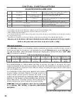
Page 35: ...r assembly I 3 ft 91 cm 3 ft 91 cm Radial clearance around service regulator vent outlet Table 3 Vent Termination Clearances Vent Termination Restrictions WARNING This appliance has been designed to draw room air and discharge heated air from the openings around the finishing edge Blocking or modifying these openings in any way can create hazardous situations Only Approved Direct Vent may be used ...

Page 36: ...nce to combustibles must be maintained around any vertical vent pipe Around a horizontal vent pipe the clearance to combustibles should be 2 51 mm above and 1 25 mm on the sides and bottom When combustible materials are directly above the first 90 elbow 12 5 318 mm of clearance is necessary Vertical Pipe to the Side Walls Horizontal Pipe to the Sides Bottom Above First Elbow Above Subsequent Elbow...

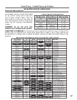
Page 37: ...5DL1 5DT 12 5D12 5D12 12 pipe length 58DVA 18 5DT 18 5D18 18 pipe length 58DVA 24 5DL2 5DT 24 5D2 5D24 24 pipe length 58DVA 36 5DL3 5DT 36 5D3 5D36 36 pipe length 58DVA 48 5DL4 5DT 48 5D4 5D48 48 pipe length 58DVA 60 60 pipe length 58DVA E30 30 elbow 58DVA E45 5DE45 5DT EL45 5D45L 5D45L 45 elbow 58DVA E90 5DE90 5DT EL90 5D90L 5D90A 5D90L 90 elbow 58DVA VSS DVA BVS VSS 5DT VS VSK 5DHVS DVSK 5DVS Vi...

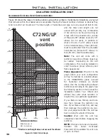
Page 38: ...vent configuration will lay Remember to consider elbows in the HORIZONTAL plane account for horizontal distance as stated above Use the corresponding exhaust restrictor accorinding to the graph See the following section in this manual for installation details Your climate and altitude may alter what restrictor is required for your particular application If your flame is low flickery and more blue ...

Page 39: ...MAY NOT BE COPIED REPRODUCED OR OTHERWISE DISCLOSED WITHOUT THE PRIOR APPROVAL OF SHERWOOD INDUSTRIES LTD EXHAUST RESTRICTOR 15 PC DESC PROCESS PATH STATION STATION 2 STATION 1 STATION 5 STATION 7 STATION 9 STATION 3 STATION 4 STATION 6 STATION 8 STATION 10 Intake Blocker Plate The C72I C72ID comes equipped with an Intake Blocker Plate installed on the far right side of the firebox bottom behind t...

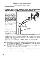
Page 40: ...Note that the termination bolts onto the flat portion of the standoff providing an air space between the wall and the vent termination The air gap prevents excessive heat from possibly melting the vinyl siding 6 Horizontal pipes must be supported every 3 914 mm Plumber s all round strap will suffice 7 Ensure venting clearances are maintained see page 36 for details Step 1 Set the fireplace in the ...

Page 41: ...n the vent termination should be pointing up Run a bead of non hardening mastic around the edges of the vent cap to make a seal with the wall Ensure the proper clearances to combustibles have been maintained Vertical Termination Step 1 Check the instructions for required clearances air spaces to combustibles when passing through ceilings walls roofs enclosures attic rafters or other nearby combust...

Page 42: ...flashing to the roof with roofing nails Use a non hardening sealant between the uphill edge of the flashing and the roof Insure the roofing material overlaps the top edge of the flashing Verify that you have at least the minimum clearance to combustibles at the roof line Step 8 Continue to add pipe sections until the height of the vent cap meets the minimum code requirements Refer to Figure 54 and...

Page 43: ...g should be framed to 10 254 mm x 10 254 mm inside dimensions in the same manner as shown in Figure 48 45 elbows x2 Wall strap Plumber s tape connected to wal strap 4 Any occupied areas above the first floor including closets and storage spaces which the vertical vent passes through must be enclosed The enclosure may be framed and sheet rocked with standard building materials However consult the a...

Page 44: ...lated from the gas supply piping system by closing its individual manual shutoff valve during any pressure testing of the gas supply piping system at test pressures equal to or less than psig 3 45 KPa Always check for gas leaks with a soap and water solution after completing the required pressure test TO TEST VALVE PRESSURES The pressure taps are located on the top right of the valve shown in Figu...

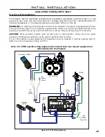
Page 45: ...move the grounding prong from this plug CAUTION When servicing controls label all wires prior to disconnection Wiring errors can cause improper and dangerous operation Verify proper operation after servicing If any of the original wire as supplied with the appliance must be replaced it must be replaced with 18 AWG wire with a temperature rating of 105 C Figure 58 C72I Wiring Diagram IFC Main Harne...

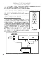
Page 46: ...installed at before or after the fireplace installation The fans are operated by the remote controller The fans can be turned on or off at anytime with the remote There are also 6 different fan speed settings The fireplace must be electrically connected and grounded in accordance with local codes or in the absence of local codes with the current CSA C22 1 Canadian Electrical Code Part 1 Safety Sta...

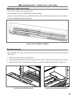
Page 47: ...firebox Figure 61 Burner Platform Installation Bezel Installation The unit comes with a set of burner bezels There are two long bezels one short and one short with a notch cutout 1 Remove the safety screen and glass door 2 Place the bezels directly onto the burner platform as shown in Figure 62 No fasteners are required 3 Ensure that the short notched bezel is placed around the pilot assembly as s...

Page 48: ... Secondary Installation 3 Wear clean vinyl gloves when handling 50 3685 Fluted and 50 3686 Ledgestone to prevent skin contact with the refractory Wear clean vinyl gloves when handling 50 3687 Enameled to prevent smudging use denatured alcohol to clean Unwrap your new Enviro liner set from the protective packaging Be careful not to scratch or bump the liners as they are very fragile If the liners a...

Page 49: ...nward Slip it into the channel behind the media tray and install the rear liner retainer 6 Place the bezel strips around the tray before the side liners are installed There are 4 horizontal glass bezel pieces and two outside bezel pieces 7 Place the side liners into the side channels of the media tray 50 3686 Ledgestone and 50 3687 Enameled will be placed in at the bottom and rotated up until seat...

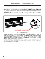
Page 50: ...3691 Driftwood Log Set see instruction sheets for further detail 10 Re install the glass door and safety screen IMPORTANT IF THE AIR SLOT AROUND THE BURNER IS BLOCKED WITH MEDIA THIS WILL CAUSE THE FIREPLACE NOT TO BURN PROPERLY AIR AIR AIR SLOT Figure 68 Burner Side Cross Section LOG 6 LOG 5 LOG 4 LOG 2 LOG 1 LOG 3 LOG 8 LOG 7 LOG 9 Log Set Installation ...

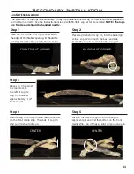
Page 51: ...m Log 1 Step 2 Place Log 2 behind Log 1 into the back right corner Log 2 will touch the back and side liners The tip of Log 2 will rest on Log 1 Step 4 Position Log 4 on Log 3 and rest the bottom on the front media strip The ends of Log 3 and Log 4 should line up FRONT RIGHT CORNER BACK RIGHT CORNER CENTER CENTER CENTER Step 1 Place Log 1 on the front right corner along the edge of the firebox ope...

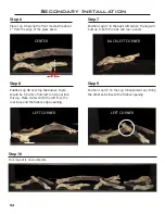
Page 52: ...r end close to the firebox opening Step 8 Position Log 8 over top the burner there should be 3 points of interest to help position this log Make contact with the left liner the rear liner and the firebox edge opening Step 10 Your log set is now complete Step 6 Place Log 6 along the front media strip about 1 from the edge of the glass bezel CENTER BACK LEFT CORNER LEFT CORNER 1 LEFT CORNER ...

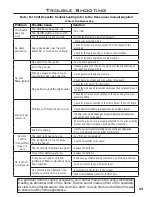
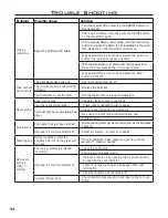
Page 53: ...rner for obstruction Check the wirings and connections between the pilot assembly and the board Check the correct gas type settings on the valve and pilot burner assembly orifice Pilot will not remain lit Problem with Flame Sensor circuit Check for proper connection of the Flame Sensor to the IFC board Check pilot for full flame impingement around Flame Sensor If flame is too small check gas press...

Page 54: ...wer temperature Flame lifting Leak in vent pipe Check for leaks in vent connections Improper vent configuration Check vent configuration with manual Terminal may be re circulating flue gases Check to see if terminal is on correctly May need to install high wind termination cap Contact dealer Blue Flames The heater has just been started Normal during start up flame will yellow as the fireplace heat...

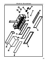
Page 55: ...55 Parts Diagram 1 2 3 4 5 6 9 7 8 12 13 14 10 15 15 ...

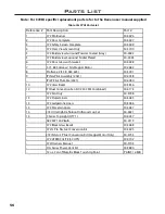
Page 56: ...I 6 5 8 3 0 5 l e z e B s s a l G 2 7 C 0 1 12 IPI Dual Convection Fan Kit 240 CFM Combined 50 4173 8 9 7 3 0 5 y l n O n a F 2 7 C 5 8 6 3 0 5 s r e n i L d e t u l F 2 7 C 3 1 6 8 6 3 0 5 s r e n i L e n o t s e g d e L 2 7 C 3 1 7 8 6 3 0 5 s r e n i L n i a l e c r o P 2 7 C 3 1 14 C72 Ultra High Definition Driftwood Log Set 50 3691 7 5 0 4 0 5 1 Y T Q t h g i L p o T s e i r e S C 5 1 50 4119...

Page 57: ...57 Notes ...

Page 58: ...58 Notes ...

Page 59: ...fety screen mesh Exclusions An expanded list of exclusions is available at www enviro com help warranty html This warranty does not cover Damage as a result of improper usage or abuse Damage caused from over firing due to incorrect setup or tampering Damage caused by incorrect installation To the Dealer Provide name address and telephone number of purchaser and date of purchase Provide date of pur...

Page 60: ..._________________________________ MODEL ___________________________________ SERIAL NUMBER ___________________________ DATE OF PURCHASE _____________ dd mm yyyy DATE OF INSTALLATION ___________ dd mm yyyy NATURAL GAS NAT PROPANE LPG INLET GAS PRESSURE _________in wc MAIN BURNER ORIFICE __________ DMS PILOT ORIFICE _________OR________in diam INSTALLER S SIGNATURE ____________________________________...

Reviews: