22
IPI SPECIFIC INSTRUCTIONS
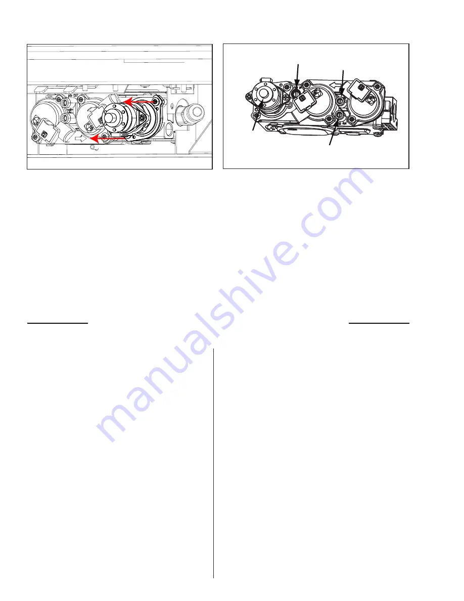
Pilot Adjustment
Screw
Manifold
Pressure Tap
Inlet
Pressure Tap
Stepper
Regulator
11.
7. Convert the SIT gas valve:
12.
Disconnect the wire harness from the IFC.
13.
Use a T-20 driver to remove the two screws that hold the servo regulator to the gas
valve. Remove the rubber regulator diaphragm that is situated between the servo regulator
and the valve body. The New servo regulator already has this diaphragm installed.
14.
Install the LP or NG servo regulator, with the new longer T-20 screws included in the kit.
15.
Re-connect the harness to the IFC.
16.
Reinstall the Burner, burner media and glass door.
1.
TESTING FOR LEAKS.
2.
Reconnect the electrical power to the unit.
3.
12. Relight the pilot and confirm the flame
properly covers both the thermocouple and
thermopile. Should the pilot require adjustment,
turn the adjustment screw clockwise to decrease
or counterclockwise to increase until the
4.
Relight the main burner in both the “HI” and
“LO” positions to verify proper burner ignition,
operation and proper flame appearance.
5.
Confirm the inlet and manifold pressures are
within the acceptable ranges as directed in section
Intial Intallation - Gas Line Connection and
Testing. If the E25 has been installed at
an altitude higher than 2000ft (610m) it is
required to de-rate the unit accordingly:
6.
In the USA: The appliance may be installed
at higher altitudes. Please refer to your American
Gas Association guidelines which state: the sea
level rated input of Gas Designed Appliances
installed at elevations above 2000 (610 m)
feet is to be reduced 4% for each 1000 feet
(305 m) above sea level. Refer also to local
authorities or codes which have jurisdiction in
your area regarding the de-rate guidelines.
7.
In Canada: When the appliance is installed at
elevations above 4500 feet (1372 m), the certified
high altitude rating shall be reduced at the rate
of 4% for each additional 1000 feet (305 m).
8.
14. MAKE SURE that the conversion
label is installed on or close to the rating
label to signify that the unit has been
converted to a different fuel type.
9.
f) Verify that if the conversion is from NG
to LPG, the screw must be re-assembled with
the red o-ring visible (refer to Figure 4). If the
conversion is from LPG to NG, The red o-ring
indicates which fuel the valve is set up for
Finalizing Conversion Nova & IPI


