33
Orifice and Pressure Information.
E25 With Log Set & Proflame Valve
Main Burner
Natural Gas
Propane Gas
Orifice:
#38 DMS
#52 DMS
Max. Manifold Press:
3.6 W.C. (0.89 KPa)
10.0” W.C. (2.49 KPa)
Min. Manifold Press:
1.6 W.C. (0.40 KPa)
6.4” W.C. (1.59 KPa)
Max. Supply Press:
7.0” W.C. (1.74 KPa)
11.0” W.C. (2.74 KPa)
Min. Supply Press:
4.5” W.C. (1.12 KPa)
10.4” W.C. (2.59 KPa)
Max. Input:
28,000 BTU/hr (8.2 KW)
28,000 BTU/hr (8.2 KW)
Min. Input:
18,500 BTU/hr (5.42 KW)
22,500 BTU/hr (6.59 KW)
NEVER USE AN OPEN FLAME FOR LEAK TESTING.
a
Djusting
t
he
p
iLot
f
Lame
:
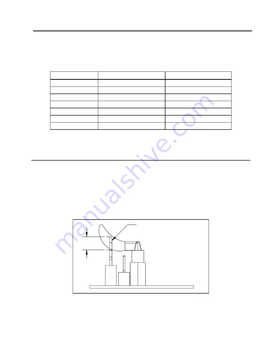
The pilot flow adjustment is set to maximum at the factory and should not need to be adjusted. The pilot
flame should envelope ⅜” to ½” (10 to 13mm) of the Flame sensor (see Figure 35). However, should the
need arise, follow Steps 1- 2 below.
1. The adjustment screw can be reached through the front of the unit using a 10 inch long blade head
screw driver (see Figure 34 for location on valve).
2. Turn the adjustment screw clockwise to decrease or counterclockwise to increase pilot flame.
Initial Installation
QUALIFIED INSTALLERS ONLY
.375-.500
(10-13mm)
Flame Sensor


