o
peRating
p
RoceDuRe
:
Initializing The System For The First Time
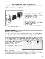
Install the four (4) AA batteries into the receiver battery bay. Note the polarity of the battery and insert into
the battery bay as indicated on the Battery cover (+/-). Place the 3-position slider switch in the “Remote”
position (see Figure 7). Using the end of a paper clip, or other similar object, insert the end of the paper clip
into the hole marked “PRG” on the Receiver front cover (see Figure 7).
The Receiver will “beep” three (3) times to indicate that it is ready to synchronize with a Transmitter. Install
the three (3) AAA type batteries in the Transmitter battery bay, located on the base of the Transmitter. With
the batteries already installed in the Transmitter, push the ‘ON’ button. The Receiver will “beep” four (4)
times to indicate the Transmitter’s command is
accepted and sets to the particular code of that
Transmitter. The system is now initialized.
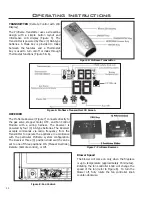
Temperature Indication Display
With the system in the “OFF” position, press the
Thermostat Key and the Mode Key at the same
time. Look at the LCD screen on the transmitter
to verify that a °C or °F is visible to the right of
the Room Temperature display (see Figure 10).
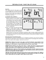
Turn on the Appliance
Press the ON/OFF Key on the Transmitter. The Transmitter display will show all active Icons on the screen. A
single “beep” from the Receiver will confirm reception of the command and will commence to first ignite the
pilot light, followed by the main burner. This should take about 10 seconds to complete.
Figure 10: Remote Control Display in Farenheit and Celcius.
Operating Instructions
R
emote
m
ounting
t
he
R
eceiVeR
(o
ptionaL
):
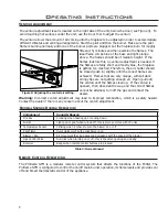
The receiver can be removed from the unit and placed inside a standard Junction type wall box or another
convenient location. This installation can take place up to 6’ft (1.8 m) from the appliance control valve.
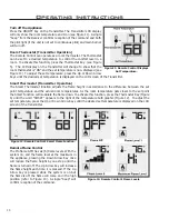
1. Connect the wiring harness to the back of the
Receiver.
2. Install the Receiver in the Junction box using the
existing J box screws (Figure 9).
3. Insert the four (4) AA type batteries in the battery
compartment with the correct polarity.
4. Place the slider into the cover plate.
5. Put the Receiver switch in the “OFF” position.
6. Make sure the Receiver and cover plate words “ON”
and “UP” are on the same side.
7. Align the slider with the switch on the Receiver and
couple the switch into the slider.
8. Align the screw holes.
9. Using the two (2) screws provided secure the cover
plate to the Receiver.
Figure 9: Wall Mounting the Receiver.
12


