background image

14

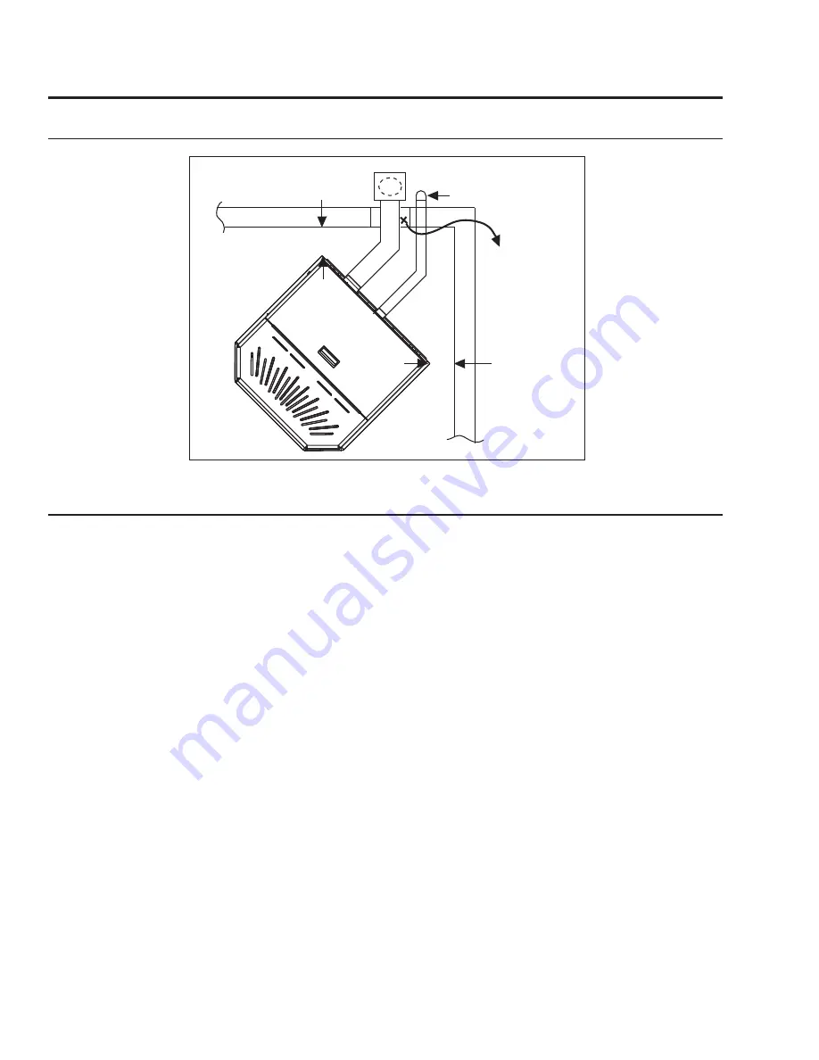
Figure 17: Corner Installation. 

3" (7.5 cm)

3"

(7.5 cm)

Fresh Air Intake

Wall thimble

manufactured

by pellet vent

manufacturer.

Installation

c

orner

 t

hrough

 W

all

 i

nStallation

 - f

reeStanding

:

h

orizontal

 e

xhauSt

 t

hrough

 W

all

 i

nStallation

 - f

reeStanding

:

Vent installation: install vent at clearances specified by the vent manufacturer.

A chimney connector shall not pass through an attic or roof space, closet or similar concealed spaces, 

or a floor, or ceiling. Where passage through a wall or partition of combustible construction is desired, 

the installation must conform to CAN/CSA-B365 Installation Code for Solid-Fuel-Burning Appliances and 

Equipment and with all local regulations, including those referring to regional and national. Only use 

venting of L or PL type with an inside diameter of 3 or 4 inches (7.6 or 10.1 cm).
1. Place the appliance 15” (37.5 cm) away from the wall. If the stove is to be set on a hearth pad, set 

the unit on it. 

2. Locate the center of the exhaust pipe on the stove. Extend that line to the wall. Once you have located 

the center point on the wall, refer to pellet vent manufacturer installation instructions for correct hole 

size and clearance to combustibles.

3. Install the wall thimble as per the instructions written on the thimble. Maintain an effective vapour 

barrier in accordance with local building codes.

4. Install a length of vent pipe into the wall thimble. Try not to have joints inside the thimble. The pipe 

should install easily into the thimble.

5. Connect  the  exhaust  vent  pipe  to  the  exhaust  pipe  on  the  stove.  Seal  the  connection  with  high 

temperature silicone.

6. Install the fresh air intake (see 

o

utSIde

 F

reSH

 a

Ir

 C

onneCtIon

)

.

7.  Push the stove straight back, leaving a minimum of 3” (76 mm) clearance from the back of the stove 

to the wall. Seal the vent pipe to the thimble with high temperature silicone.

8.  The  pipe  must  extend  at  least  12”  (30  cm)  away  from  the  building.  If  necessary,  bring  another 

length of pipe to the outside of the home to connect to the first section. Do not forget to place high 

temperature silicone around the pipe that passes through the thimble.

Summary of Contents for OLYMPIAN

Page 1: ...NS COULD RESULT IN PROPERTY DAMAGE BODILY INJURY OR EVEN DEATH Contact your building or fire officials about restrictions and installation inspection requirements in your area OLYMPIAN F R E E S T A N...

Page 2: ...Vertical Rise with Horizontal Termination Installation Recommended Freestanding 16 Through Concrete Wall With Vertical Rise Installations Freestanding 16 Inside Vertical Installations Freestanding 17...

Page 3: ...ing a pellet burning appliance If it sounds the alarm correct the cause but do not deactivate You may choose to relocate the smoke detection devise within the room DO NOT REMOVE THE SMOKE DETECTOR FRO...

Page 4: ...wer bar is recommended The unit must be grounded The grounded electrical cord should be connected to a standard 220 240 volts 2 92 3 18 Amps 50 hertz electrical outlet and also must be accessible If t...

Page 5: ...e operation of the pellet stove Do not burn with insufficient combustion air A periodic check is recommended to ensure proper combustion air is admitted to the combustion chamber Setting the proper co...

Page 6: ...FPI 115 C 239 F Fuel Consumption High Fuel Consumption Medium Fuel Consumption Low FS 2 3 kg hr 5 07 lb hr FPI 2 2 kg hr 4 85 lb hr FS 1 4 kg hr 3 09 lb hr FPI 1 4 kg hr 3 09 lb hr FS 0 7 kg hr 1 54 l...

Page 7: ...m 24 3 4 629mm Figure 1 Olympian Freestanding Dimensions Figure 2 Olympian Fireplace Insert Dimensions Dimensions Fireplace Insert Specifications Dimensions Freestanding 7 23 3 4 604mm 12 7 8 326mm 22...

Page 8: ...ches 180 cm cross sectional area 5 This unit must not be installed directly onto carpet If it is to be installed on a carpeted area a solid surface wood metal or approved hearth pad must be installed...

Page 9: ...mpian on Floor Protection Minimum Width 36 914mm Minimum Height 48 1219mm Maximum Depth 30 762mm Back wall Side wall Adjacent wall 3 76mm 3 76mm 6 152mm Installation Clearances to Combustibles Freesta...

Page 10: ...our T 20 screws see Figure 10 The back height of this unit can be set to one 1 of three 3 heights 19 483 mm 21 537 mm 22 565 mm The hopper should be set to the maximum height that can be used in the i...

Page 11: ...Ensure the unit is electrically grounded to the chassis of your home permanently WARNING Do not install in a room people sleep in CAUTION The structural integrity of the manufactured home floor wall...

Page 12: ...ermination locations Table 2 Use in conjunction with Figure 13 for allowable exterior vent termination locations Letter Minimum Clearance Description A 24 in 61 cm Above grass top of plants wood or an...

Page 13: ...9 1 16 229mm Outside fresh air is mandatory when installing this unit in airtight homes and mobile homes A Fresh air intake is strongly recommended for all installations Failure to install intake air...

Page 14: ...r of the exhaust pipe on the stove Extend that line to the wall Once you have located the center point on the wall refer to pellet vent manufacturer installation instructions for correct hole size and...

Page 15: ...cting the vent pipe to the unit s starter pipe Improper seals at the vent joints may cause combustion byproducts to leak into the room where installed seal as required Installation Figure 18 Straight...

Page 16: ...elbow may be used in place of the termination cap or stainless steel termination hood Through Concrete Wall With Vertical Rise Installations Freestanding A 45 elbow may be used in place of the termina...

Page 17: ...peted surface and space the unit in a manner so when the pellet vent is installed vertically it will be 3 76 mm away from a combustible wall 3 Locate the center of the fresh air intake pipe on the uni...

Page 18: ...a tee with clean out on the outside of the house 2 Install PL vent upward from the tee Make sure that you install support brackets to keep the vent straight and secure 3 Install ceiling thimble and se...

Page 19: ...ould com from chimney If holes already exist fresh air intake can be taken through back of the fireplace or through the ash dump Installation Hearth Mount Installation Freestanding Figure 24 Hearth Mo...

Page 20: ...r the gasketed opening in the stove where the exhaust motor was removed from 4 Install the exhaust blower motor in the Exterior Vent Housing Box onto the exhaust blower housing 5 Follow the procedures...

Page 21: ...y spaced and a small bead of high temperature silicone at each chimney connection Also ensure that all vertical vent sections are properly supported and that all clearances to combustibles are maintai...

Page 22: ...ation Outside Vertical Installations Freestanding Ensure that vent pipe is properly secured to wall using wall straps Maintain clearances to combustibles on vent pipe as well as unit Rain Cap Roof she...

Page 23: ...OT cut or modify any factory firebox parts If the fireplace insert does not fit into a zero clearance fireplace we recommend you use an ENVIRO freestanding model and install as a hearth mounted unit I...

Page 24: ...e Figure 31 REMOVAL When maintenance is required on the unit the surround must be removed Pull the surround straight up till it stops then pull it out about 4 10 cm and rest the surround on top of the...

Page 25: ...of trim Refer to Figure 34 Close both cab sides and replace the two 2 screws on each side REMOVAL OF TOP TRIM With door open undo the two 2 screws on the underside of the top there are visible under...

Page 26: ...7 Inner side of Olympian door Plated Door Installation TO AVOID PERSONAL INJURY DO NOT REMOVE OR REPLACE COVER WHEN PELLET STOVE IS HOT REMOVAL OF LOUVER BAR SET Door must be open The three 3 arrows i...

Page 27: ...inside the firebox will increase as the combustion exhaust blower increases in speed higher heat output setting If the fire should happen to go out and the heat output indicator has been set on the lo...

Page 28: ...t and has a higher possibility of the fire building up and creating clinkers hard ash build up Taking a reading of vacuum pressure inside the firebox with a magnehelic gauge can be used to set the sli...

Page 29: ...ealer for service 2 The stove will not operate when hot Check the Heat Level Indicator if a fire is not detected or if the fire has gone out the 3 light will flash because the Exhaust Temperature Sens...

Page 30: ...the vacuum switch if this corrects the problem check for above problems before replacing the Vacuum Switch Damage to gray wires between Circuit Board and Vacuum Switch Inspect wires and connectors Com...

Page 31: ...When the units system light becomes solid then control of the unit is given back to the operator If there is no control of the Heat Level button make sure the thermostat is calling for heat Call your...

Page 32: ...llow Yellow Grey Grey Grey Grey Purple Purple Blue 115V Black 220V Brown Black Black Black Blue Black Armor Cable Supplied Vacuum Switch Combustion Blower Optional Exterior Exhaust Blower Power Cord G...

Page 33: ...EF 018 Aluminum Hose Barb EF 019 7 Auger EF 025 Auger Brass Bushing Plate post January 2008 50 1780 8 Door Handle Complete EF 028 9 Glass Set with Tape EF 062 10 Slider Damper Plate EF 064 11 Brass A...

Page 34: ...0 825 30 Ash Pan Insert 50 826 31 Hopper Lid Insert 50 827 32 Hopper Cover Insert 50 828 33 300 Watt Ignitor 220V 50 1583 34 Circuit Board 5 Amp Fuses 220V Pair 50 834 Exhaust Starter Tube 80mm diamet...

Page 35: ...im 1 piece Antique Copper Freestanding 50 665 46 Upper Cabinet Trim 1 piece Painted Freestanding 50 666 46 Upper Cabinet Trim 1 piece Gold Freestanding 50 667 46 Upper Cabinet Trim 1 piece Pewter Free...

Page 36: ...OLYMPIAN Components January 2008 4 10 1 35 6 2 11 7 5 3 38 34 26 37 39 14 36 Parts Diagram Components 36...

Page 37: ...37 OLYMPIAN Freestanding Steel Parts September 2015 9 44 8 43 16 17 25 40 33 18 12 23 24 41 19 22 15 20 21 46 45 47 42 Parts Diagram Freestanding Steel...

Page 38: ...OLYMPIAN Insert Steel Parts September 2015 50 52 51 54 55 53 48 49 32 31 29 47 28 30 27 13 Parts Diagram Insert Steel 38...

Page 39: ...RCHASE _____________ dd mm yyyy DATE OF INSTALLATION ___________ dd mm yyyy MAGNEHELIC AT INSTALL ___________________ INSTALLER S SIGNATURE _________________________________________ NAME OF INSTALLER...

Reviews: