ENVIRO-TEC
16
FORM ET115.24-NOM4 (819)
SECTION 1 - RECEIPT & INSTALLATION
FIELD FURNISHED AND INSTALLED PIPING
OR RISERS
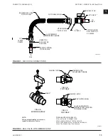
Units provided for field furnished and installed water
and drain piping or risers include the flex hose and ball
valve assemblies previously described. These hose
and valve assemblies include a stub of copper tube for
field connection to the unit piping. The factory hose
and valve assemblies are marked by connection type
and retracted inside the unit for shipment. Do not braze
the pipe stub without opening the ball valve and dis-
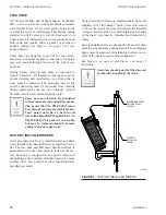
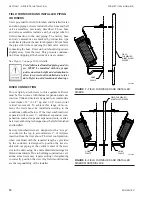
connecting the hose. Riser stub out should slope down
slightly away from the riser. This prevents condensa-
tion from dripping at the bottom of a riser column.
See
Figure 7 on page 16
for details.
Field fabricated/installed piping and ris-
ers MUST be installed with the proper
unit connection height and orientation to
allow for correct unit installation at a later
date. Refer to unit dimensional drawings.
RISER CONNECTION
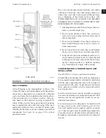
Do not rigidly attach risers to this equipment. Risers
must be free to move with thermal expansion and con-
traction. Units and risers are designed to accommodate
a maximum of 3” (1-1/2” up and 1-1/2” down) total
vertical movement. To achieve this range of move-
ment, the risers must be installed according to the
conditions outlined below. If the total combined riser
expansion will exceed 3”, additional expansion com-
pensation, such as loops and expansion joints, or alter-
nate riser anchoring techniques must be field furnished
and installed.
Factory furnished risers are designed with a “swage”
or socket in the top to accommodate 2” of tailpiece
insertion from the riser above. The riser configuration,
when combined with the required length as provided
by the customer, is designed to position the riser-to-
unit stub out piping at the vertical center of the riser
slot in the unit casing.
See unit submittal drawings for
dimensional details
.
Due to building construction vari-
ations, some risers may require cutting or lengthening
to correctly position the riser. Any field modifications
are the responsibility of the installer.
& INSTALLED
RISERS
FIELD
FURNISHED
HOSE
CLAMP
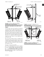
FIGURE 7 -
FIELD FURNISHED AND INSTALLED
RISERS
& INSTALLED RISERS
FIELD FURNISHED
HOSE
CLAMP
HOSE
CLAMP
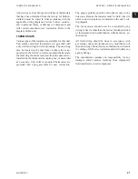
FIGURE 8 -
FIELD FURNISHED AND INSTALLED
RISERS MASTER/SLAVE
LD13874
LD13875
Summary of Contents for VHA
Page 10: ...ENVIRO TEC 10 FORM ET115 24 NOM4 819 THIS PAGE INTENTIONALLY LEFT BLANK ...
Page 41: ...ENVIRO TEC 41 SECTION 2 START UP FORM ET115 24 NOM4 819 THIS PAGE INTENTIONALLY LEFT BLANK ...
Page 54: ...ENVIRO TEC 54 FORM ET115 24 NOM4 819 SECTION 6 Dimensional Data 74 80083 ...
Page 78: ...ENVIRO TEC 78 FORM ET115 24 NOM4 819 SECTION 6 Dimensional Data NOTES ...

