ENVIRO-TEC
18
FORM ET115.24-NOM4 (819)
SECTION 1 - RECEIPT & INSTALLATION
FIELD RECONFIGURABLE RISERS AND
DISCHARGE OPENINGS
Riser Reconfiguration
Vertical Hi-Rise units are furnished with riser slot
“knockouts” in the casing back and both sides. Should
it be necessary to relocate risers in the field, the water
risers may be disconnected at the swivel joint on the
riser isolation valve, and removed from the unit. The
drain riser may be removed by moving the drain tube
hose clamp and removing the riser tube from the drain
hose.
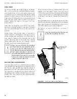
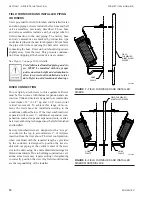
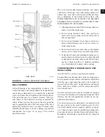
The water riser slot “knockouts” may be removed by
clipping the “tabs” to separate the inner portion of the
knockout. See
Figure 9 on page 18
for details
.
After
opening the riser slot, make a vertical slit in the cabinet
insulation with a sharp utility knife. This slit must be
centered left to right, and full height in the slot. The
water riser may now be re-installed at the desired loca-
tion by inserting the valve through the new opening.
Insert the valve through the opening with care to avoid
damage to the cabinet insulation. Make sure that the
swivel joint O-ring is undamaged, and re-attach the
hose to the valve with the O-ring in place. Replace-
ment O-rings (Part No. PR-07-0115) may be ordered
through the parts department.
INSULATION
SLIT CABINET
AS REQ'D
CLIP "TABS"
AS
REQ'D
CLIP
"TABS"
AS REQ'D
DRYWALL
STOP
FOLD OUT
FIGURE 9 -
KNOCKOUT REMOVAL
LD13876
After relocating all the risers, pressure test the joints to
assure system integrity.
The drain riser slot is already present on the back, left
and right sides. To install the drain riser, insert the riser
tube into the unit and connect the drain hose using the
hose clamp preciously removed.
After all the risers have been relocated, inspect the
cabinet insulation where the risers were removed, and
repair any insulation damage before starting the unit
and cover unused openings.
DISCHARGE OPENING RECONFIGURATION
Vertical Hi-Rise and Tandem Master & Tandem Slave
units are furnished with discharge opening “knock-
outs” in all four sides and the top. Should it be nec-
essary to reconfigure a unit for a different discharge
arrangement than originally provided, the new dis-
charge opening may be created by clipping the tabs of
the desired opening to remove the inner portion of the
“knockout”. The side flanges may then be folded out to
provide the drywall stops for the opening. See
Figure 9
on page 18
for details.
After the new opening is created, the cabinet insulation
must be trimmed out, and the edges of the insulation
should be coated with duct board adhesive or appropri-
ate liner tape to prevent erosion into the airstream.
Any unused discharge openings must have the drywall
stops bent back flush with the unit casing. The open-
ing must then be covered with an insulated plate. Any
cover plates and insulation must be provided and in-
stalled by others.
Relocating a discharge opening on a double discharge
unit may require removal or relocation of any factory
provided sight and sound baffle. Consult the factory
for details on requirements and relocation of sight and
sound baffles.
Size 10 and 12 units factory furnished
with double discharge do not have dis-
charge “knockouts” to allow field conver
-
sion to a single discharge. Consult the
factory for details.
The manufacturer assumes no responsibility for unde-
sirable system operation due to improper field design,
equipment or component selection, and/or installation
of ductwork, grilles, and other related components.
Summary of Contents for VHA
Page 10: ...ENVIRO TEC 10 FORM ET115 24 NOM4 819 THIS PAGE INTENTIONALLY LEFT BLANK ...
Page 41: ...ENVIRO TEC 41 SECTION 2 START UP FORM ET115 24 NOM4 819 THIS PAGE INTENTIONALLY LEFT BLANK ...
Page 54: ...ENVIRO TEC 54 FORM ET115 24 NOM4 819 SECTION 6 Dimensional Data 74 80083 ...
Page 78: ...ENVIRO TEC 78 FORM ET115 24 NOM4 819 SECTION 6 Dimensional Data NOTES ...

