ENVIRO-TEC
39
SECTION 2 - START-UP
FORM ET115.24-NOM4 (819)
2
Procedure for Checking ECM Constant
Torque Wiring Harnesses
1.
Remove power from the unit. Lock and tag out
power source.
2.
Verify that equipment is properly grounded.
3. Unplug ECM Motor Power wiring harness, and
use ohmmeter to verify continuity (see
Table 12
on page 39
for details.)
4. Verify continuity from green wire (motor ground)
to equipment ground.
5. Unplug ECM Motor Signal wiring harness, and
use ohmmeter to verify continuity (see
Table 13
on page 40
for details.)
6. Replace all connections. Ensure good connections
are made.
Only very light force is required when
inserting meter probe into plug. Excess
force will damage contacts.
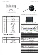
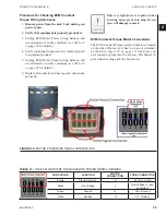
ECM Constant Torque Motor Connections
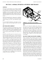
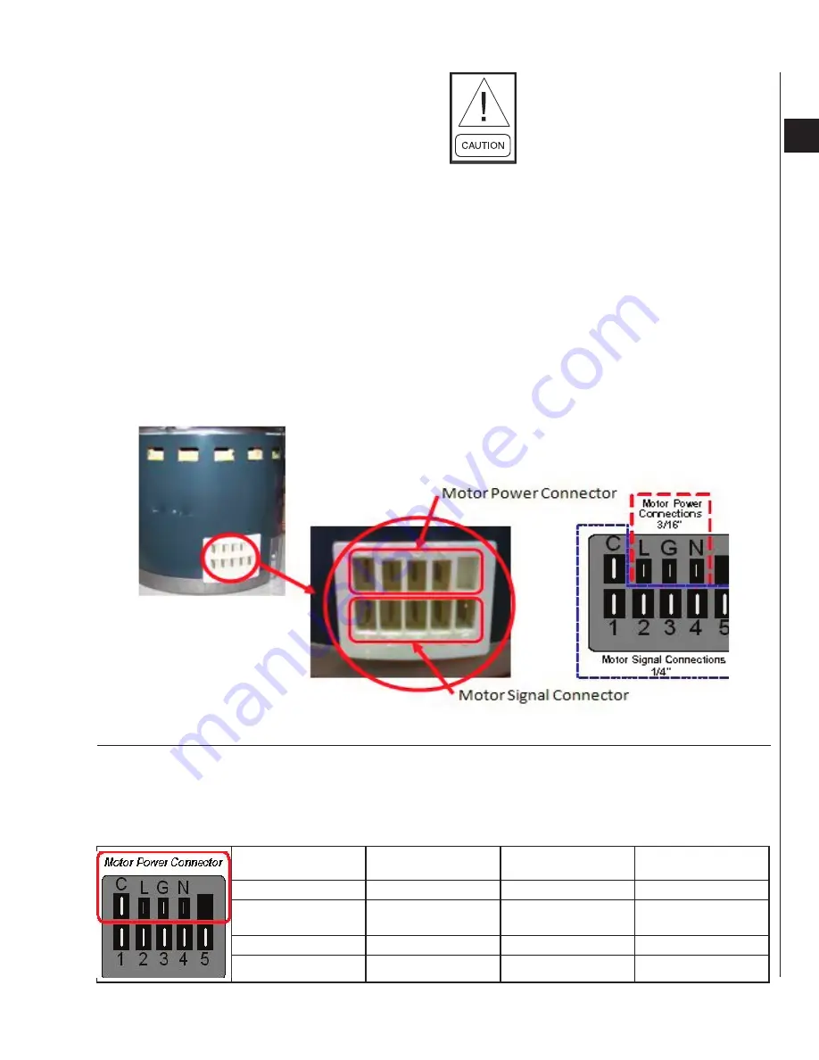
The ECM Constant Torque motor connector is located
on the side of the motor. It has two rows of terminals,
as shown in
Figure 29 on page 39
. The Power (4-
pin) connector plugs into the top row. The Signal (5-
pin) connector plugs into the bottom row.
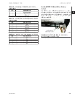
FIGURE 29 -
MOTOR POWER AND SIGNAL CONNECTORS
TABLE 12 -
THE ECM CONSTANT TORQUE MOTOR POWER WIRING HARNESS
WIRE COLOR
FUNCTION
MOTOR
CONNECTION
FCRB CONNECTION
Purple
Signal Common
C
24 VAC - COM
Black
Line Voltage
L
Line Voltage In - see
equipment
Green
Ground
G
N/A - Ground
White
Neutral
N
P1 - L2/Neut
Summary of Contents for VHA
Page 10: ...ENVIRO TEC 10 FORM ET115 24 NOM4 819 THIS PAGE INTENTIONALLY LEFT BLANK ...
Page 41: ...ENVIRO TEC 41 SECTION 2 START UP FORM ET115 24 NOM4 819 THIS PAGE INTENTIONALLY LEFT BLANK ...
Page 54: ...ENVIRO TEC 54 FORM ET115 24 NOM4 819 SECTION 6 Dimensional Data 74 80083 ...
Page 78: ...ENVIRO TEC 78 FORM ET115 24 NOM4 819 SECTION 6 Dimensional Data NOTES ...

