ENVIRO-TEC
43
SECTION 3 - NORMAL OPERATION & PERIODIC MAINTENANCE
FORM ET115.24-NOM4 (819)
3
MUST be corrected immediately. High supply voltage
also causes excessive amperage draw and may result in
tripping of the circuit breaker or blowing of the fuses
on the incoming power supply.
Window treatments and drapes must not
be positioned in a manner which obstructs
the air flow through the return air or dis
-
charge grilles.
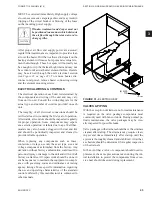
After proper air flow and supply power are assured,
regular filter maintenance is important to provide clean
air over the heater. Dirt that is allowed to deposit on the
heating element will cause hot spots and eventual ele-
ment burn-through. These hot spots will normally not
be enough to trip the thermal high limit and may not
be evident until actual heater element failure. Heaters
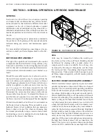
may be serviced through the unit’s electrical section
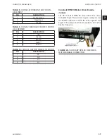
(see
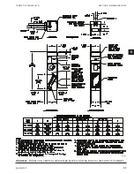
Figure 31 on page 43
)
.
To remove heater, dis-
connect unit power, remove heater connecting wiring
and the element mounting screws.
ELECTRICAL WIRING & CONTROLS
The electrical operation of each unit is determined by
the components and wiring of the unit and may vary
from unit to unit. Consult the wiring diagram for the
actual type and number of controls provided on each
unit.
The integrity of all electrical connections should be
verified at least twice during the first year of operation.
Afterwards, all controls should be inspected regularly
for proper operation. Some components may experi-
ence erratic operation or failure due to age. Wall ther-
mostats may also become clogged with dust and lint
and should be periodically inspected and cleaned to
provide reliable operation.
When replacing any components such as fuses,
contactors, or relays, use only the exact type, size, and
voltage component as furnished from the factory. Any
deviation without factory authorization could result in
personnel injury or damage to the unit and will void all
factory warranties. All repair work should be done in
such a manner as to maintain the equipment in compli-
ance with governing codes and ordinances or testing
agency listings. More specific information regarding
the use and operating characteristics of the standard
controls offered by this manufacturer is contained in
other manuals.
TYP
(6) PLCS
FIGURE 31 -
ELECTRIC HEAT
VALVES & PIPING
With the exception of strainers, no formal maintenance
is required on the valve package components most
commonly used with fan coil units. During normal pe-
riodic maintenance, the valve packages may be visu-
ally inspected for possible leaks.
Valve packages with strainers should have the strainers
cleaned after startup. The strainers may require clean-
ing several times immediately after startup until the
system is thoroughly cleaned and stabilized. After that,
a schedule should be determined for regular inspection
of the strainers.
In the event that a valve or component should need re-
placement, the same precautions taken during the ini-
tial installation to protect the components from exces-
sive heat should observed during replacement.
LD13878
Summary of Contents for VHA
Page 10: ...ENVIRO TEC 10 FORM ET115 24 NOM4 819 THIS PAGE INTENTIONALLY LEFT BLANK ...
Page 41: ...ENVIRO TEC 41 SECTION 2 START UP FORM ET115 24 NOM4 819 THIS PAGE INTENTIONALLY LEFT BLANK ...
Page 54: ...ENVIRO TEC 54 FORM ET115 24 NOM4 819 SECTION 6 Dimensional Data 74 80083 ...
Page 78: ...ENVIRO TEC 78 FORM ET115 24 NOM4 819 SECTION 6 Dimensional Data NOTES ...

