ENVIRO-TEC
48
FORM ET115.24-NOM4 (819)
SECTION 5 - TROUBLESHOOTING
SECTION 5 - TROUBLESHOOTING
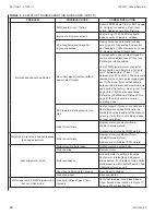
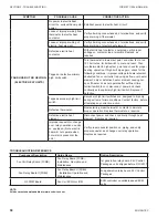
SYMPTOM
POSSIBLE CAUSE
CORRECTIVE ACTION
NO UNIT OPERATION
No power to unit.
Apply proper power to unit.
Improper power to unit.
Apply proper power to unit and check for damaged
components and/or blown fuses, if furnished.
Power distribution panel
switch or circuit breaker in
“OFF” position.
Turn power distribution panel switch or circuit breaker to
“ON” position.
Unit toggle or door interlock
disconnect switch in “OFF”
position.
Turn unit toggle or door interlock disconnect switch to
“ON” position.
Fan switch or thermostat
system switch in “OFF”
position.
Turn fan switch or thermostat system switch to “ON”
position.
Blown or defective unit main
fuse, if furnished.
Check for possible defective component or improper
wiring, and replace fuse.
Blown or defective fan motor
fuse, if furnished.
Check for possible defective component or improper
wiring, and replace fuse.
Defective toggle, door
interlock, fan, or thermostat
system switch.
Momentarily jumper suspected component to simulate
closed contacts and achieve unit operation. Replace
defective device with known good part.
Loose or improper wiring
from power distribution and/
or remote mounted control
devices.
Verify all wiring connections and terminations, and verify
proper wiring of all incoming power devices and remote
mounted controls.
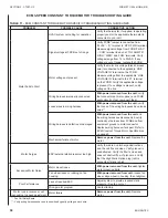
UNIT BLOWS MAIN UNIT OR
FAN MOTOR FUSE WHEN
POWER IS APPLIED TO UNIT
Defective or improperly wired
component.
Using a battery powered continuity tester, check for
shorted or grounded components starting at incoming
power. Note position of all controls during various
component checks. Caution: some voltages have
isolated common which may not show a short to chassis
ground. Be sure to isolate each control to eliminate
faulty reading through a parallel wired component.
FAN DOES NOT RUN WITH
POWER TO UNIT
Fan switch in “OFF” position.
Turn fan switch to “ON” position.
Thermostat system switch in
“OFF” position.
Turn thermostat system switch to “ON” position.
Remote “start/stop” switch in
“OFF” position.
Turn remote “start/stop” switch to “ON” position.
Loose or improper wiring from
fan switch or thermostat to
unit.
Verify all wiring connections and terminations, and verify
proper wiring of all control devices.
Loose or improper wiring from
remote “start/stop” switch to
unit “start/stop” relay.
Verify all wiring connections and terminations, and verify
proper wiring of remote “start/stop” switch.
Defective fan switch.
Momentarily jumper fan switch to each fan speed wire to
simulate proper fan switch operation. Replace defective
fan switch.
Defective “start/stop” relay.
Momentarily jumper “start/stop” relay to simulate proper
relay operation. Replace defective “start/stop” relay.
Defective fan motor.
Verify proper fan switch operation and replace defective
fan motor.
Summary of Contents for VHA
Page 10: ...ENVIRO TEC 10 FORM ET115 24 NOM4 819 THIS PAGE INTENTIONALLY LEFT BLANK ...
Page 41: ...ENVIRO TEC 41 SECTION 2 START UP FORM ET115 24 NOM4 819 THIS PAGE INTENTIONALLY LEFT BLANK ...
Page 54: ...ENVIRO TEC 54 FORM ET115 24 NOM4 819 SECTION 6 Dimensional Data 74 80083 ...
Page 78: ...ENVIRO TEC 78 FORM ET115 24 NOM4 819 SECTION 6 Dimensional Data NOTES ...

